When OEM engineers, product designers, or sourcing managers evaluate custom stamped metal components, one of the first questions directed to a supplier is often straightforward: “What metal stamping tolerances can you hold?”
A responsible manufacturing supplier cannot answer that question with a single universal number.
In custom metal stamping, there is no single standardized tolerance that applies across every part, every material, or every feature. Achieving and maintaining dimensional accuracy depends on a combination of part geometry, material alloy and temper, material thickness, feature type, tooling design, press stability, tool wear, and even the inspection method used to verify the finished component.
Understanding how tolerances behave in progressive, compound, and single-station die stamping helps engineers set realistic drawing callouts, prevent unnecessary production costs, and ensure part repeatability across full manufacturing runs.
What Are Metal Stamping Tolerances?
Metal Stamping Tolerance Quick Reference
| Feature Type | Typical Tolerance Consideration | Main Influencing Factors |
|---|---|---|
| Hole Diameter | Controlled by punch and die condition | Tool wear, clearance, material thickness |
| Hole Location | Depends on strip feeding accuracy | Pilot pins, die alignment |
| Bend Angle | Affected by springback | Material hardness, grain direction |
| Overall Length | Depends on forming stability | Part geometry, tooling rigidity |
| Flatness | Influenced by residual stress | Material properties, forming sequence |
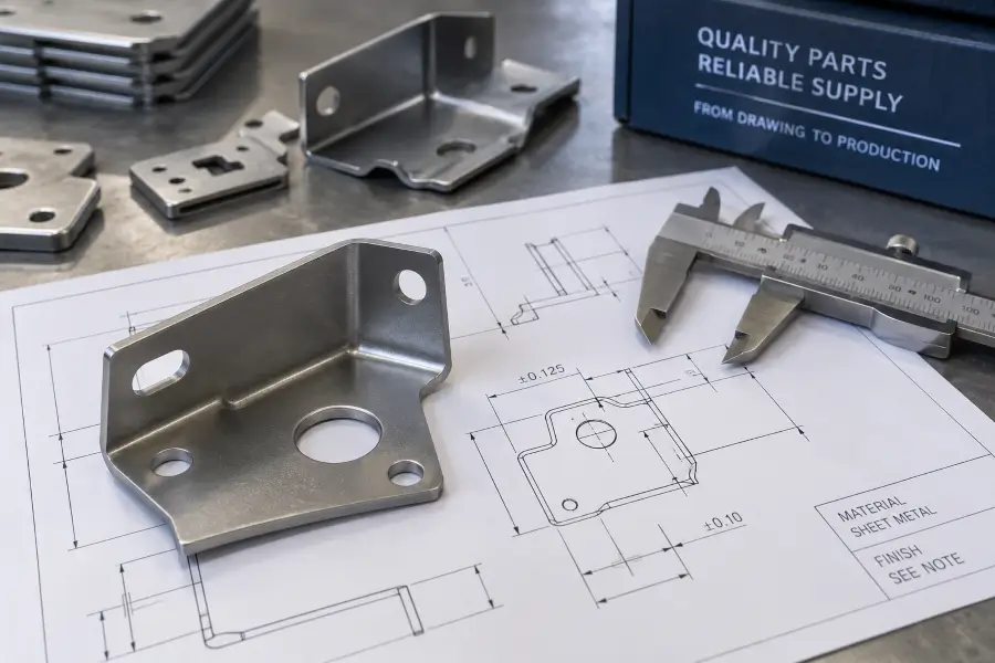
In custom sheet metal stamping, dimensional tolerance represents the total allowable variation from a specified nominal dimension on an engineering drawing. It defines the acceptable boundaries within which a stamped feature must fall to ensure proper assembly, structural integrity, and functional performance.
On a stamped part drawing, tolerances are typically specified in two main forms:
- General Tolerances: Broad dimensional allowances that apply to un-toleranced dimensions across the entire part, often defined in the title block or by referencing a general drafting standard.
- Feature-Specific Tolerances: Specific dimensional limits assigned to individual critical features—such as a hole diameter, a pin location, or a critical mating slot—where precise dimensional control is required for function or assembly.
Understanding these boundaries requires recognizing the difference between nominal dimensions (the targeted ideal measurement), the upper and lower limit dimensions (the absolute limits of acceptability), and the actual physical variation created by the stamping process.
What Tolerances Can Metal Stamping Achieve?
Because sheet metal stamping relies on mechanical shear, plastic deformation, and punch-and-die clearances, achievable tolerances vary significantly based on the feature being produced.
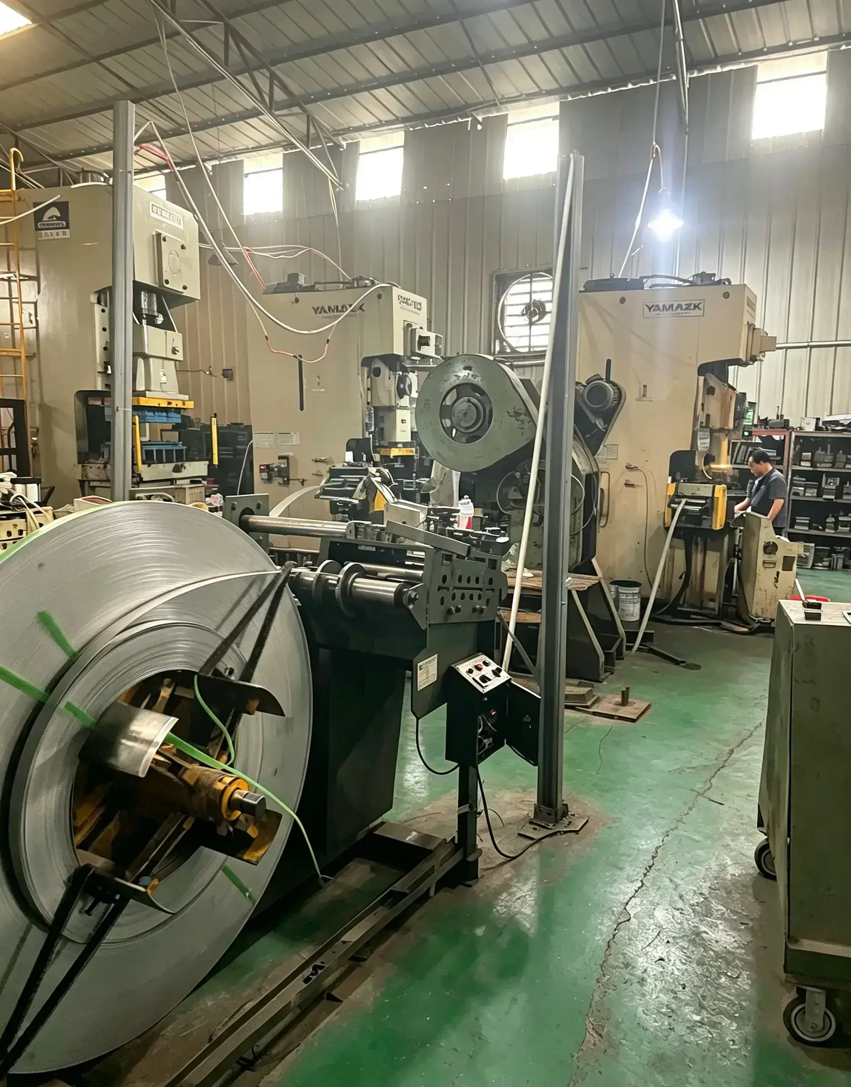
Based on our production experience at Metal Stamp Factory, general linear dimensions on many custom stamped parts can be controlled within approximately ±0.05 mm to ±0.10 mm (±0.002 in to ±0.004 in) when the part geometry, material selection, tooling construction, and manufacturing process conditions are suitable.
It is vital to recognize that this ±0.05 mm to ±0.10 mm range reflects shop production experience under controlled conditions—it is not a universal industry standard or a blanket guarantee for every stamped design.
Practical Drawing Expectations vs. Theoretical Limits
In real-world OEM procurement, functional performance rarely requires extreme precision on every feature.
For example, in one U.S. customer engineering drawing we reviewed, the tightest specified dimensional tolerance was ±0.125 mm (approximately ±0.005 in). This is simply one practical drawing example that illustrates how a functional part drawing does not necessarily require ultra-tight tolerances across all dimensions, rather than a universal standard for all stamped parts.
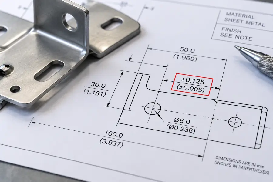
Unnecessarily tight tolerances can increase tooling requirements, process-control demands, inspection effort, and overall production cost without necessarily adding functional value to the final product.
Why Tolerance Varies by Stamped Feature
A common source of confusion during drawing review is assuming that if a stamping supplier can hold a tight tolerance on a pierced hole, that same tolerance can automatically be applied to an overall formed length or a bend angle.
Stamping forces sheet metal through distinct deformation mechanisms, each with its own inherent dimensional stability:
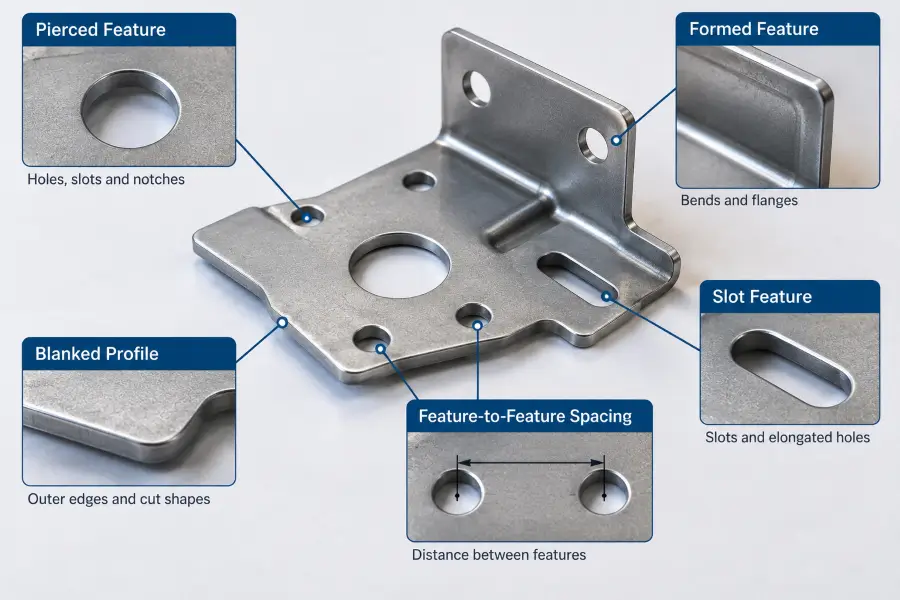
Pierced Features (Holes, Slots, and Notches)
Dimensions produced purely through shearing—such as hole diameters and pierced slot widths—can often be controlled more directly by tooling geometry than dimensions created primarily through bending or forming. Because shearing is directly governed by punch and die dimensions, pierced features generally maintain predictable consistency.
Cut Profiles and Blank Outer Edges
Blanking and trimming operations cut the outer perimeter of the component. While still controlled by die shearing, blank profile dimensions are subject to die edge wear over large production volumes and minor variation in carrier strip progression within progressive dies.
Feature-to-Feature Spacing
The distance between two features produced in the same die station (such as two holes pierced simultaneously in a compound die) can be held to tight tolerances. However, the distance between features produced across different die stations in a progressive die relies on strip feeding accuracy, pilot pin alignment, and material strip flexure.
For more details on how compound die and progressive die architectures influence feature relationships and dimensional control, see our comparison of compound die vs progressive die tooling.
Formed Features and Bends
Dimensions that involve plastic deformation and bending—such as flange heights, bend angles, and channel widths—exhibit wider natural variation than sheared features. Formed dimensions are subject to material tensile strength variation, sheet thickness tolerances, grain orientation, and springback after the punch retracts.
What Determines Achievable Stamping Tolerance?
Achieving repeatable dimensions in high-volume metal stamping requires managing several interrelated physical and operational factors:
Material and Thickness
Raw coil stock is subject to mill manufacturing tolerances in both thickness and yield strength. Thicker materials require larger punch-and-die clearances, which increases shear zone rollover and fracture variation. Material hardness and temper directly influence springback behavior during forming.
Part Geometry
Complex three-dimensional parts with multiple adjacent bends, deep draws, or narrow web sections between features experience internal material stresses during stamping. Unbalanced part geometry can cause localized metal stretch or distortion, making tight linear tolerances more challenging to maintain without secondary restriking.
Die Design and Tooling Condition
Tooling construction and stamping die design dictate long-term process capability. Die guidance, punch-and-die condition, alignment, clearance, and overall tooling rigidity directly influence how consistently dimensions are held over extended production runs.
Press and Production Stability
The mechanical condition of the stamping press—including stroke repeatability, bolster deflection under tonnage, gib clearance, and feed system pitch accuracy—directly affects part dimensions. A worn press or an unstable strip feeding mechanism introduces variability that cannot be compensated for by die design alone.
Springback and Forming Behavior
When sheet metal is bent or formed, it undergoes elastic deformation alongside plastic deformation. Once the stamping press stroke completes and the die pressure releases, the material relaxes slightly toward its original shape. Because coil material properties vary slightly from heat to heat, springback angles fluctuate naturally during production.
Tool Wear During Production
As production continues, punches and die cutting edges gradually wear. Cutting edge wear alters the cutting condition, increases burr formation, and can gradually affect dimensional consistency over extended production runs. Tool maintenance and sharpening schedules are essential for preserving dimensional control over long production runs.
Metal Stamping Tolerance Standards: What Do They Actually Mean?
Engineers often reference international or trade standards on drawing title blocks. However, it is essential to understand what these standards actually govern in relation to metal stamping tolerances:
For a broader guide to drawing-level requirements, including title-block tolerances, GD&T, burr, flatness, finish, and revision control, see our stamped part drawing notes guide.
DIN 6930
DIN 6930 can serve as a relevant reference for stamped-part tolerance specifications where applicable. The specific applicability of its guidance should always be confirmed based on the engineering drawing, material selection, and applicable standard revision.
ISO 2768
ISO 2768 is a general tolerance framework widely used on engineering title blocks for linear and angular dimensions. While common in general drafting, it is not tailored to sheet metal stamping physics and should not be treated as a direct measure of metal stamping process capability.
ASME Y14.5 and ISO 1101
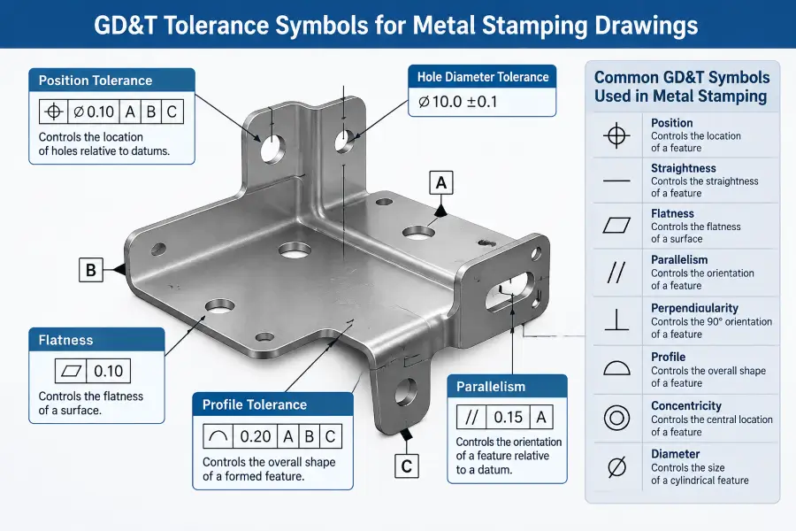
Standards such as ASME Y14.5 and ISO 1101 establish the geometric dimensioning and tolerancing (GD&T) language used to define feature control frames, datums, position, profile, and flatness. These frameworks define how tolerance requirements are symbolically communicated on engineering drawings—they do not guarantee or define physical manufacturing capability.
GD&T vs Traditional Dimensional Tolerances
| Method | Purpose | Typical Application |
|---|---|---|
| Linear Tolerance | Controls size variation of individual dimensions | Length, width, hole diameter |
| Position Tolerance | Controls feature location relative to datums | Mounting holes and assembly features |
| Flatness | Controls surface variation | Mounting surfaces and contact areas |
| Profile | Controls complex feature geometry | Formed sheet metal components |
Supplier Capability vs. Drawing Requirements
A formal standard provides a baseline reference, and a drawing specifies what the designer requires. However, actual production capability depends on the specific combination of tooling quality, material behavior, press stability, and quality control during manufacturing.
Tight Tolerances vs. Practical Production Tolerances
In engineering design, specifying tighter tolerances than necessary is a primary driver of inflated manufacturing costs.
When a drawing specifies an unnecessarily tight tolerance across non-critical features, the overall production process becomes significantly more sensitive. Maintaining tighter limits generally demands higher tooling precision, tighter process control, more frequent tool maintenance, and more rigorous inspection procedures.
If a tight tolerance is genuinely critical to the part’s function, mechanical fit, or assembly, those additional controls are necessary and fully justified. However, if the feature merely provides clearance or structural support, assigning an over-constrained tolerance increases tooling investment and unit costs without delivering practical engineering benefits.
Tighter tolerances can increase manufacturing cost when they require higher tooling precision, tighter process control, additional inspection effort, more frequent verification or maintenance, or additional process steps.
How Tolerance Requirements Affect Manufacturing Cost
| Requirement | Manufacturing Impact |
|---|---|
| Standard tolerances | Normal tooling and inspection requirements |
| Tight dimensional tolerances | Higher tooling precision and process control |
| Critical GD&T requirements | Additional fixture and measurement requirements |
| Excessively tight tolerances | Increased cost without additional functional benefit |
The goal of functional design for stamping is not to achieve the tightest possible theoretical dimension, but to establish a robust, repeatable production process that meets all performance requirements at the lowest practical cost.
How Are Stamping Tolerances Verified?
Dimensional verification ensures that physical parts emerging from the press match the tolerances defined on the engineering drawing.
For the broader workflow covering first article, in-process checks, final inspection, sampling, reporting, and acceptance, see our metal stamping quality inspection guide.
Common Inspection Equipment for Stamped Parts
| Inspection Equipment | Typical Application |
|---|---|
| Caliper | General dimensions and routine production checks |
| Micrometer | Thickness and precision measurements |
| CMM | Complex geometry and positional accuracy |
| Gauge Fixture | Repeatability checking during mass production |
| Optical Measurement System | Small precision features and profile inspection |
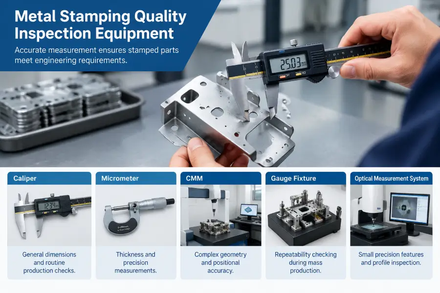
Measurement equipment and inspection methods must be matched appropriately to the feature type and the required tolerance resolution. For many routine hardware stamping dimensions, calipers are practical inspection tools when their resolution and measurement method are suitable for the specified tolerance. Micrometers or other suitable measuring equipment may be used where the feature and tolerance require them.

Prior to starting a mass production run, a first-piece verification against the engineering drawing ensures that die setup and tool alignment fall within specified limits before proceeding with manufacturing.
When Stamping Alone May Not Be the Best Choice
While custom metal stamping is an efficient method for producing high-volume sheet metal parts, certain extreme feature requirements fall outside the economic capability of standard die forming.
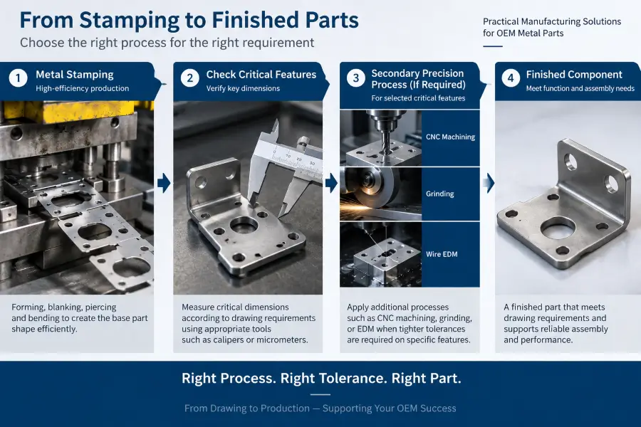
If a specific feature requires a level of precision, surface finish, or squareness that cannot be held consistently through press stamping alone, engineers should evaluate an optimized manufacturing route rather than forcing the entire component into an unachievable stamping specification.
Depending on the feature, practical alternative approaches include:
- Stamping Plus Secondary Machining: Stamping the general part profile and formed geometry, followed by secondary precision drilling, reaming, or CNC milling on selected critical features.
- Secondary Precision Grinding: Stamping flat blanks followed by double-disc grinding to achieve tight thickness or surface parallelism requirements.
- Specialized Tooling Methods: Utilizing fine blanking techniques or specialized shaving operations when extremely straight edge profiles are mandatory.
It is worth noting that processes like Electrical Discharge Machining (EDM) and Wire EDM are extensively used alongside stamping—not as replacements for high-volume stamping production, but as primary methods for manufacturing the precision tool and die components that make metal stamping possible.
How OEM Buyers Should Specify Stamping Tolerances
Understanding OEM Drawing Tolerance Requirements
| Drawing Requirement | Recommendation |
|---|---|
| Critical Dimensions | Clearly identify features that affect assembly, fit, or function |
| General Tolerance | Avoid applying unnecessarily tight tolerances to non-critical dimensions |
| GD&T Requirements | Define datums and geometric controls for critical features |
| Surface Requirements | Specify finish requirements when they affect performance or assembly |
To achieve an optimal balance between part performance, manufacturing feasibility, and production cost, OEM engineers and sourcing managers should consider the following practical guidelines when preparing drawing packages:
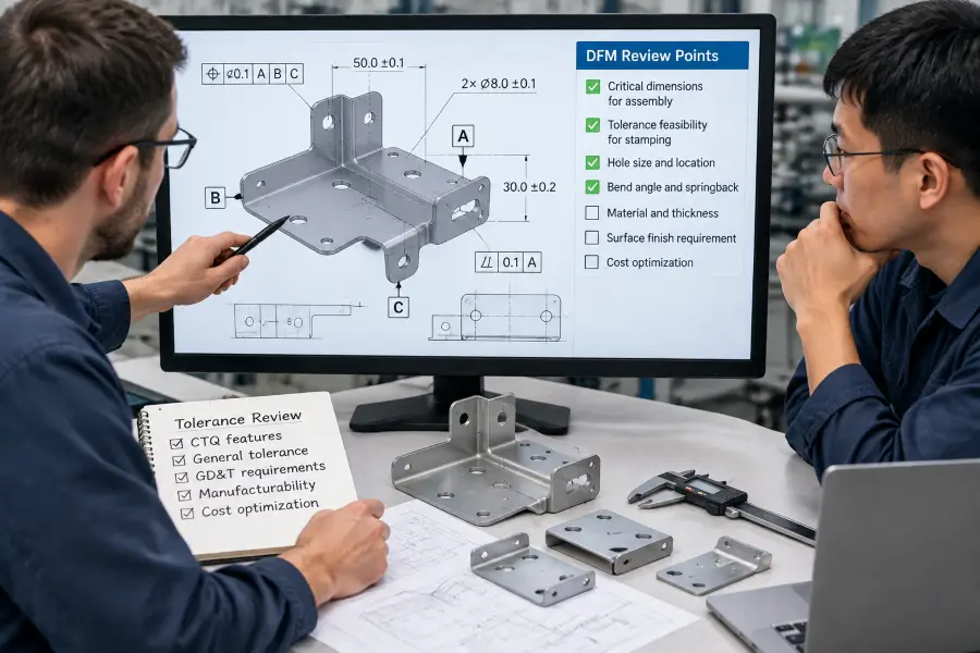
- Distinguish Critical Features from General Dimensions: Clearly identify features that govern assembly fit, seal alignment, or function as Critical to Quality (CTQ) on the drawing. Allow standard, looser tolerances on non-critical clearance edges and body profiles.
- Account for Feature Type in Tolerance Callouts: Avoid applying a single uniform tolerance block across the entire print. Allow wider dimensional allowances on formed angles, bend heights, and drawn features than on flat pierced holes.
- Identify Functional and Assembly-Critical Dimensions: Focus design precision on features that directly affect component fit, mating alignment, or mechanical performance, ensuring that detailed drawing and GD&T requirements are clearly communicated.
- Engage the Stamping Supplier Early During Design for Manufacturability (DFM) Review: Submit preliminary engineering drawings to the stamping manufacturer prior to final tooling release. A collaborative Design for Manufacturability (DFM) review allows tool engineers to identify tight-tolerance features that can be relaxed or modified to simplify tooling design and reduce unit cost.
Frequently Asked Questions
What is a typical tolerance for metal stamping?
There is no single typical tolerance for metal stamping. Based on Metal Stamp Factory’s production experience, many general dimensions on custom stamped parts have been controlled within approximately ±0.05 mm to ±0.10 mm (±0.002 in to ±0.004 in) when part geometry, material selection, tooling, process conditions, and measurement conditions are suitable. This reflects factory production experience rather than a universal industry standard, and formed or feature-specific dimensions must always be evaluated from the actual engineering drawing.
Can metal stamping hold ±0.01 mm?
For selected critical features, our production experience has included tighter tolerances under specific tooling, process, and measurement conditions. However, this should not be interpreted as a general tolerance for an entire stamped part, nor should it be assumed for routine hardware stamping without evaluating the actual drawing and feature geometry.
Why are formed dimensions harder to control than pierced features?
Pierced features are created directly by cutting tool geometry, making them relatively consistent. Formed dimensions involve plastic bending and elastic recovery (springback). Because raw material coils vary slightly in yield strength, hardness, and thickness from lot to lot, formed angles and flange heights exhibit greater natural variation after leaving the die.
Which standards apply to metal stamping tolerances?
DIN 6930 can be a relevant tolerance reference for stamped parts where applicable. Standards like ISO 2768 provide a general tolerance framework for engineering drawings but should not be treated as a direct statement of stamping process capability. Standards such as ASME Y14.5 and ISO 1101 provide frameworks for defining geometric tolerance requirements on drawings. Applicable standards, drawing requirements, and actual supplier capability must always be evaluated separately.
Does tighter tolerance increase metal stamping cost?
Tighter tolerances can increase manufacturing cost when they require higher tooling precision, tighter process control, additional inspection effort, more frequent verification or maintenance, or additional process steps. Tight tolerances are fully justified when required by actual part function or assembly, but applying them unnecessarily to non-critical features increases production costs without adding engineering value.
How should I specify tolerances for a stamped part drawing?
Apply strict tolerances only to essential mating or functional dimensions, use standard process allowances for general profiles, clearly identify critical features, and allow your stamping supplier to conduct a DFM feasibility review before finalizing the drawing for tooling production.
Summary
The right metal stamping tolerances are not simply the smallest numbers a supplier claims it can hold. It is the tolerance that fully satisfies the component’s functional and assembly requirements while allowing consistent, repeatable manufacturing at the required production volume.
By understanding how material behavior, feature geometry, and tooling design influence dimensional control, OEM engineering teams can design cost-effective stamped parts that perform reliably throughout their service life.
If you are developing a new stamped component or reviewing drawing callouts for an upcoming production run, contact Metal Stamp Factory’s engineering team to request a comprehensive DFM and tolerance feasibility review.