
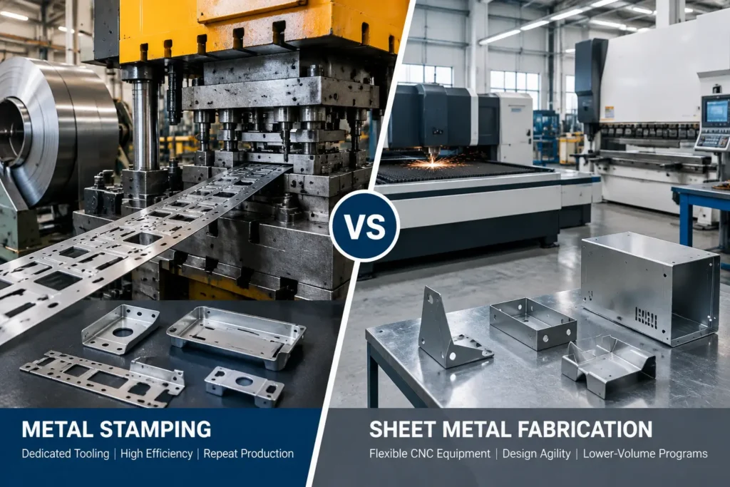
When evaluating manufacturing processes for sheet-formed metal components, OEM engineers, product designers, and procurement managers frequently evaluate metal stamping vs sheet metal fabrication. Both approaches convert flat sheet metal into functional three-dimensional components, structural brackets, enclosures, and chassis. However, they rely on fundamentally different production logic, equipment infrastructure, tooling investments, and cost structures.
Selecting the appropriate manufacturing route requires looking beyond individual piece-part quotes. A complete technical and economic evaluation must consider component geometry, annual production requirements, design maturity, tooling capital, material utilization, and total program lifecycle costs. Choosing between metal stamping and sheet metal fabrication is rarely a matter of identifying a universally superior process; rather, it involves aligning part design specifications and business objectives with the inherent capabilities and economic profiles of each manufacturing route.
Metal Stamping vs Sheet Metal Fabrication: Quick Comparison
The following core technical and operational distinctions summarize how flexible sheet metal fabrication compares with custom metal stamping for OEM production.
| Factor | Metal Stamping | Sheet Metal Fabrication |
|---|---|---|
| Manufacturing Method | Uses dedicated dies in presses for cutting, forming, and shaping operations | Uses flexible CNC equipment including laser cutting, punching, bending, and welding |
| Tooling Investment | Higher upfront die development cost | Low setup cost using standard machine tooling |
| Production Volume | Best suited for high-volume repeat programs | Suitable for prototypes, low-to-mid volumes, and changing designs |
| Design Flexibility | Limited after tooling release due to fixed die geometry | High flexibility through CAD and machine program changes |
| Unit Cost Trend | Decreases significantly as volume increases | Remains relatively stable because labor and machine time dominate |
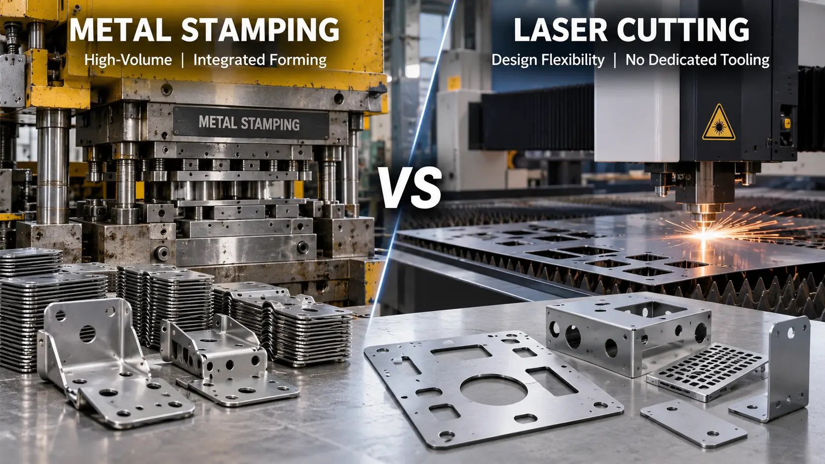
Manufacturing Approach Sheet metal fabrication relies on flexible CNC work centers—such as laser cutters, turret punch presses, press brakes, and welding stations—to process sheet metal through sequential discrete operations. Custom metal stamping utilizes dedicated tool sets (dies) mounted in presses to execute cutting, piercing, flanging, and forming operations simultaneously or in rapid continuous progression.
Tooling Investment Sheet metal fabrication requires minimal non-recurring engineering (NRE) tooling investment because operations utilize standard, universal tooling already installed on CNC machinery. Custom metal stamping requires dedicated die sets, which involve significant upfront capital expenditure and development lead time to design, machine, assemble, and qualify.
Production Strategy Sheet metal fabrication is structured around flexible batch processing, making it well suited for prototypes, low-to-mid volume production runs, custom industrial assemblies, and programs with evolving design revisions. Custom metal stamping is engineered for continuous repeat production, distributing initial tooling costs across larger production quantities to lower ongoing labor and unit costs.
Design Flexibility Sheet metal fabrication provides high design agility, allowing geometry changes to be implemented primarily through software and machine program updates without modifying hard tooling. Custom metal stamping fixes part geometry within hardened tool steel dies, meaning design revisions require physical die modifications, insert replacements, or re-machining.
Understanding the Difference Between Metal Stamping and Sheet Metal Fabrication
To make informed manufacturing decisions, sourcing teams must first clarify the terminology and structural relationship between metal stamping and sheet metal fabrication.
A common misconception in OEM procurement is treating metal stamping and sheet metal fabrication as mutually exclusive, competing categories of manufacturing. In industrial practice, sheet metal manufacturing represents the overarching category of industrial processes that cut, bend, form, and join sheet metal stock. Metal stamping is a specialized, tool-dedicated manufacturing method contained within the broader sheet metal processing landscape.
The distinction between conventional sheet metal fabrication and custom metal stamping lies in how mechanical force is applied to the raw material to achieve the final geometry. Fabrication relies primarily on flexible, computer-numerically-controlled (CNC) equipment that processes sheet metal sequentially using standardized tooling. Metal stamping relies on custom-engineered, dedicated die sets mounted in mechanical or hydraulic presses to perform shearing, blanking, bending, and deep drawing operations simultaneously or in rapid succession.
What Is Sheet Metal Fabrication?
Sheet metal fabrication is a flexible, multi-step manufacturing approach that transforms flat sheet metal into completed components through a sequence of discrete operations. The conventional fabrication workflow utilizes flexible CNC machinery, including high-speed laser cutters, CNC turret punches, press brakes, press-joining hardware equipment, and manual or robotic welding stations.
Key characteristics of flexible sheet metal fabrication include:
- Low non-recurring engineering (NRE) setup costs, as operations utilize universal tooling such as standard press brake V-dies, laser cutting optics, and standard punch shapes.
- High geometric agility, allowing design changes to be implemented efficiently by updating CAD files and machine programs without altering physical tooling.
- Sequential processing, where parts move between individual work centers—such as laser cutting, deburring, bending, tapping, and welding—as discrete manufacturing steps.
- Suitability for prototypes, low-to-mid volume production runs, custom industrial assemblies, and evolving product designs.
What Is Metal Stamping?
Metal stamping is a tool-dedicated, high-speed manufacturing method that utilizes hardened steel tool sets (dies) installed in mechanical, hydraulic, or servo-driven presses. Stamping processes cold-formed or hot-formed flat sheet metal, coiled strip, or discrete blanks by forcing the material into or through precision-machined tool cavities.
Key characteristics of custom metal stamping include:
- Dedicated tooling investment, requiring custom-designed progressive dies, transfer dies, or compound stage tools engineered specifically for a single component geometry.
- High press speeds and short cycle times, capable of producing completed or near-completed components in a single press stroke or through automated progressive stations.
- Consolidated manufacturing operations, where cutting, piercing, forming, coining, embossing, and drawing are integrated into a single continuous die sequence.
- High process repeatability, as part features are dictated directly by the precision-ground surfaces of hardened tool steel punches and die cavities.
Flexible Manufacturing vs Dedicated Tooling
The core operational and business decision between fabrication and stamping comes down to flexible equipment vs dedicated tooling investment.
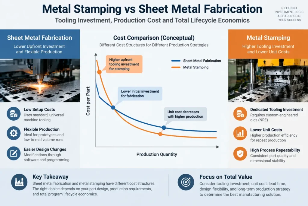
Flexible sheet metal fabrication minimizes upfront capital risk. Because it uses standard machine configurations, initial setup costs remain minimal. However, because parts are produced through sequential CNC operations—such as guiding a laser head along a perimeter or executing individual bends on a press brake—the machine time and labor content per part remain relatively high. Consequently, the unit cost curve for fabricated components remains flat over production volume increases.
Custom metal stamping reverses this economic structure. Stamping requires significant upfront capital commitment and lead time to design, machine, assemble, and qualify dedicated die sets. However, once the tooling is commissioned, the unit production time drops dramatically. A progressive die operating in an automated press line can achieve high production rates from continuous coil stock. This distributes the fixed machine time and labor across large production quantities, resulting in a lower unit cost profile for high-volume programs.
Process and Equipment Comparison
Examining the machinery and operational workflows of each process highlights how part geometry is realized on the factory floor.
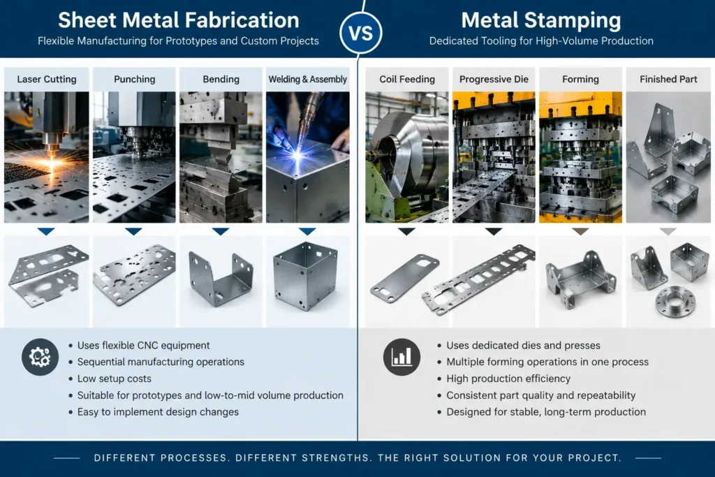
Sheet Metal Fabrication: Laser Cutting, Punching, Bending and Welding
The traditional sheet metal fabrication route relies on a series of standalone CNC work centers, each contributing specific geometric features to the component:
- Cutting and Piercing: Flat blank profiles are generated using CNC laser cutting machines or CNC turret punch presses. Laser cutters utilize focused thermal energy to cut complex perimeters, slots, and internal cutouts without physical tool wear. Turret punches cut material using indexing carousels filled with standard round, square, or slotted punch-and-die sets, making them efficient for repeating hole patterns or light louvers.
- Bending and Forming: Blanks are transferred to CNC press brakes, where hydraulic or electric rams force the sheet metal into standard lower V-dies to create linear bends, flanges, and hemmed edges. Each bend angle and flange length is formed individually, requiring part handling, repositioning, and sequence programming by an operator or automated robot arm.
- Hardware Insertion and Secondary Operations: Fasteners such as threaded standoffs, studs, and nuts are pressed into pre-punched holes using specialized insertion equipment. Countersinking, deburring, and edge-rounding are often completed as separate secondary steps.
- Joining and Assembly: Component structures requiring enclosed box shapes, internal stiffeners, or multi-part joinery are assembled using resistance spot welding, gas metal arc welding (GMAW), gas tungsten arc welding (GTAW), or structural riveting.
Metal Stamping: Progressive Dies, Transfer Presses and Dedicated Tooling
Metal stamping consolidates multiple forming and shearing operations into a single press mechanism using specialized tool architectures:
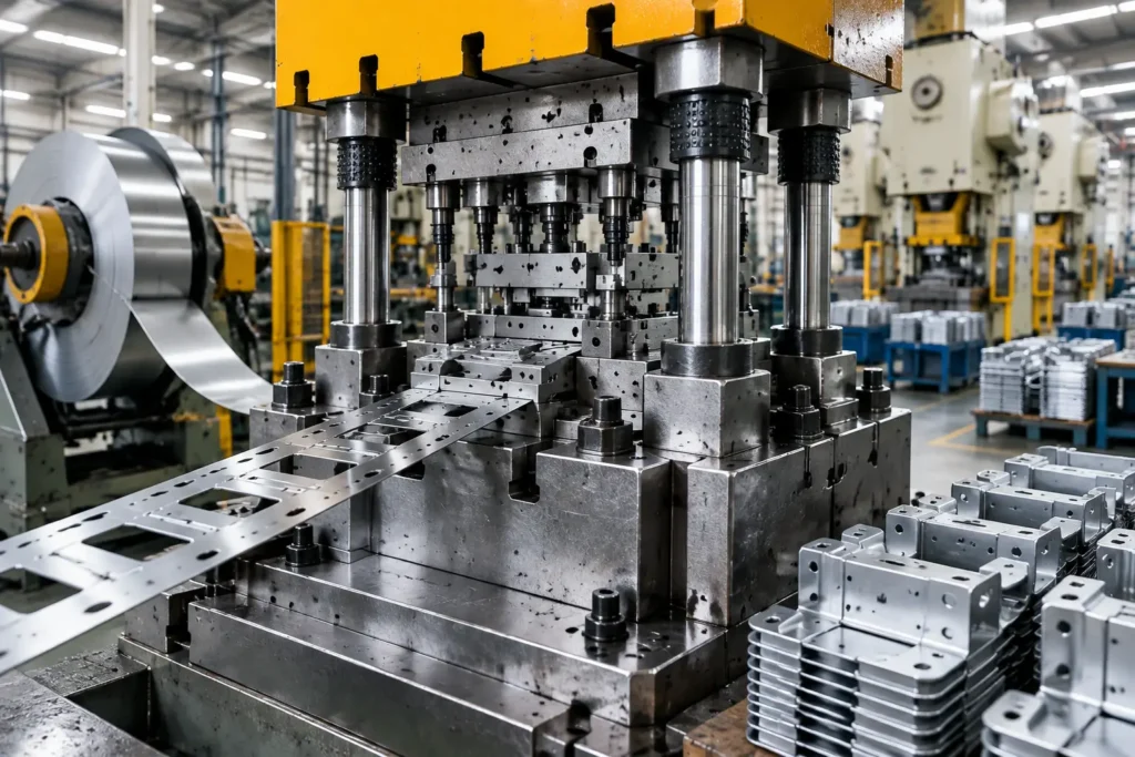
- Progressive Die Stamping: The most common configuration for high-rate sheet metal production. Continuous coil stock feeds automatically into a mechanical press. With each stroke of the press, the sheet metal advances incrementally through sequential stations within a single die set. Early stations perform piercing, slotting, and notch operations, while middle stations execute bending, flanging, and coining. The final station detaches the finished part from the carrier strip.
- Transfer Die Stamping: Used for larger components or complex geometries that cannot remain attached to a continuous strip. Discrete sheet metal blanks are fed into the press, and mechanical transfer arms carry the individual parts sequentially through a series of distinct die stations within the press bed.
- Compound and Stage Tooling: Individual die sets mounted in separate presses perform specific heavy-forming, deep-drawing, or blanking operations. Stage tooling is often used for structural sheet components where part size or tonnage requirements exceed the feasibility of a single progressive die block.
Automation, Repeatability and Production Workflow
The degree of process automation and workflow continuity varies considerably between the two methods:
- Production Workflow Continuity: Fabrication involves discrete batch processing. Sheet metal plates are cut on a laser, stacked on pallets, moved to press brakes for bending, moved again to welding stations, and finally routed to finishing operations. Stamping operates as a continuous, linear workflow where raw coil stock enters one end of the press and fully formed components exit at the other.
- Process Repeatability: Dimensional accuracy in fabrication depends on machine positioning precision, material thickness consistency, press brake back-gauge positioning, and operator handling. In metal stamping, part-to-part consistency depends directly on the mechanical accuracy of the hardened die cavity, punch-to-die clearances, press ram parallelism, and raw material springback control.
- Labor Content: Sheet metal fabrication typically requires higher touch labor per unit produced to manage loading, bending sequences, welding, and material transfer between stations. Metal stamping relies on higher upfront engineering and toolmaker labor during die construction, but operates with minimal direct touch labor once automated press lines are running.
Tooling Investment, NRE and Manufacturing Economics
Evaluating the financial trade-offs between stamping and sheet metal fabrication requires analyzing non-recurring engineering (NRE) tooling investment alongside complete lifecycle unit costs.
Low Setup Cost vs Dedicated Die Investment
The primary economic barrier in custom metal stamping is the initial investment required for dedicated tooling. Hardened tool steel progressive dies, transfer dies, and stage tools require extensive computer-aided design, precision wire electrical discharge machining (EDM), CNC tool milling, manual fitting, and iterative press tryouts. Depending on part complexity, size, stroke sequence, and material specification, custom stamping tooling requires substantial capital expenditure and development lead time.
In contrast, sheet metal fabrication requires minimal upfront tooling expenditure. Standard V-dies, laser cutting nozzles, standard turret tooling, and press brake clamps are already installed on standard plant machinery. Setup costs are generally limited to offline CAM programming, nesting optimization, machine loading, and initial line clearance. This enables rapid prototype execution and fast production launches without committing significant capital.
| Cost Factor | Metal Stamping | Sheet Metal Fabrication |
|---|---|---|
| Initial Investment | High due to custom die design, machining, assembly, and tryout | Low because standard CNC equipment is already available |
| Setup Cost | Die preparation and process validation | CAD programming, nesting, and machine setup |
| Low Volume Economics | Tooling cost may not be fully amortized | More competitive because no dedicated tooling is required |
| High Volume Economics | Lower unit cost through high-speed production | Higher labor and machine time per part |
| Long-Term Program | Strong advantage for stable production | Better for flexible or evolving programs |
Material Utilization and Piece-Part Economics
Material utilization represents a major contributor to ongoing piece-part economics:
| Factor | Metal Stamping | Sheet Metal Fabrication |
|---|---|---|
| Material Source | Coil, strip, or sheet stock optimized through strip layout | Flat sheet stock optimized through CAD nesting |
| Waste Source | Carrier strips, blanking scrap, and die layout limitations | Unused sheet areas, skeleton waste, and cutting paths |
| Optimization Method | Progressive die strip layout and material utilization engineering | Nesting software and sheet arrangement optimization |
| Best Advantage | High efficiency for stable repeat production | Flexible material usage for mixed part production |
- Nesting Yield in Fabrication: CNC laser cutters and turret punches utilize dynamic software nesting algorithms to tile irregular component shapes across large standard sheet sizes (e.g., 4×8 ft or 5×10 ft plates). This allows high material yield across mixed production orders, reducing scrap rates for complex profiles.
- Strip Layout Yield in Stamping: Progressive stamping dies process continuous coil stock using a fixed strip layout. Material must be left between adjacent part blanks and along outer edge rails to maintain carrier strength as the strip advances through sequential stations. While stamping engineers optimize strip layouts to maximize yield, part geometry and carrier requirements may lead to higher engineered material scrap compared to nested laser cutting.
- Production Cycle Times: Fabrication cycle times are calculated in minutes or seconds per part, bounded by laser feed rates, press brake stroke sequences, and manual welding times. Stamping press speeds are measured in strokes per minute (SPM), yielding completed parts in fractions of a second during high-speed runs. This reduction in unit production time offsets the higher initial tooling capital when production quantities are sufficiently high.
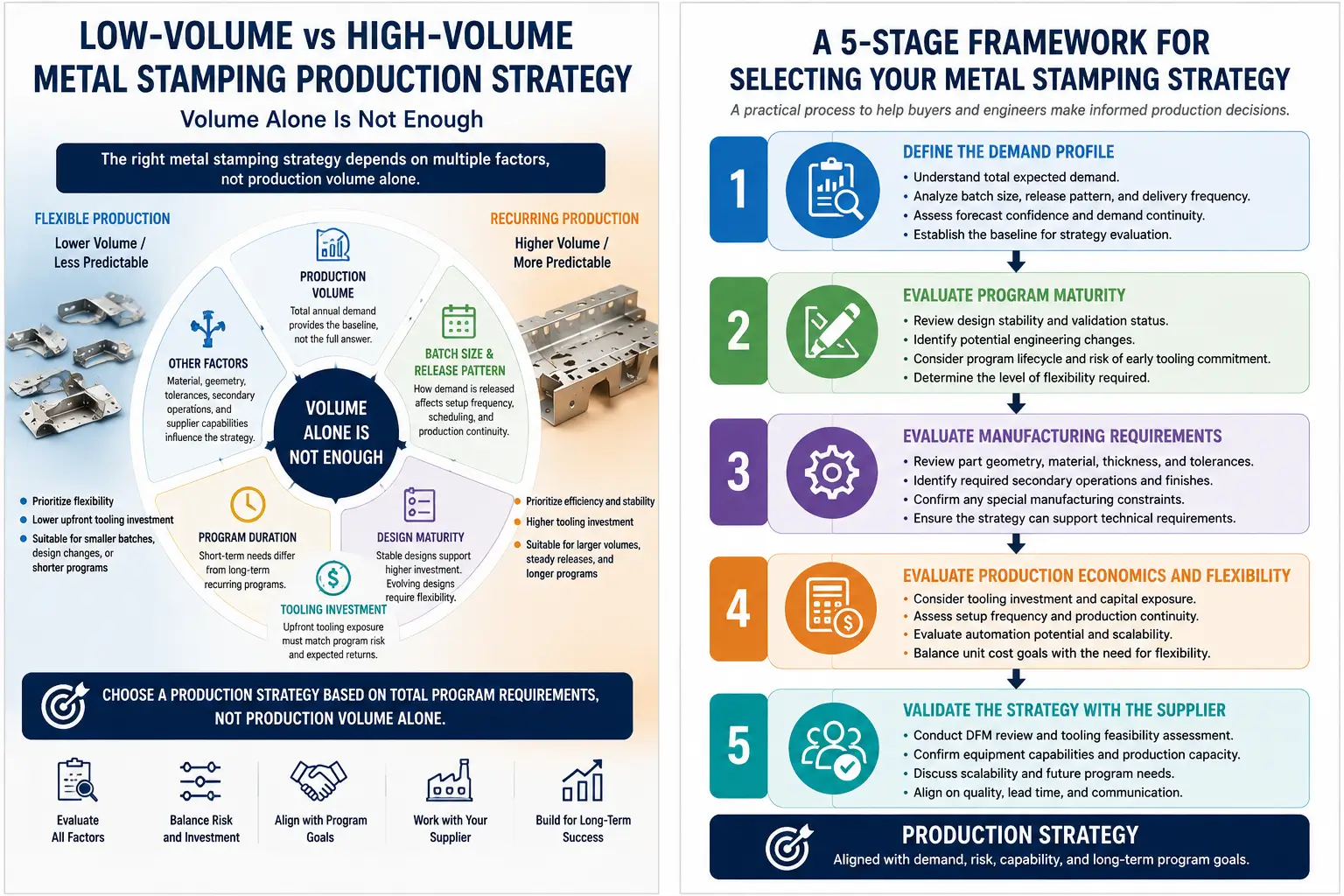
Why Production Crossover Depends on Program Requirements
A common misconception in procurement is the belief in a universal production volume threshold that automatically dictates when to switch from fabrication to stamping.
In practice, an absolute crossover volume does not exist. The precise economic threshold where progressive stamping tooling becomes justified over sheet metal fabrication varies widely from program to program. It depends on an interplay of factors:
- Part Size and Complexity: A small, highly intricate connector bracket requiring eight distinct bends, countersinks, and lanced tabs on a press brake may justify progressive stamping dies at relatively modest volumes. Conversely, a large, simple flat panel with two linear bends may remain far more economical to manufacture via CNC laser and press brake up to much higher quantities.
- Material Thickness and Alloy Type: Processing heavy-gauge steel plate or tough stainless steel grades incurs different tool wear profiles, press tonnage requirements, and laser processing speeds, shifting the economic intersection point.
- Amortization Period and Lifecycle Horizon: A multi-year production program allows the upfront NRE cost of a stamping die to be amortized smoothly over hundreds of thousands of parts, yielding a low total cost per unit. A short-lifecycle product or an evolving design may never recover the capital cost of a hard die regardless of monthly volume.
Design Flexibility and Geometry Considerations
Component design specifications directly influence which manufacturing route is technically viable and economically sensible.
When Sheet Metal Fabrication Provides More Flexibility
Sheet metal fabrication provides distinct advantages during early product development, low-volume commercial production, and programs subject to ongoing design iterations:
- Prototypes and Early-Stage Launch: Fabrication is commonly used for initial physical prototypes, design validation, and early production builds. Engineers can test form, fit, and functional assembly in real-world conditions without risking capital on hard tooling.
- Agile Engineering Change Orders (ECOs): If a mounting hole must shift, a flange length needs extension, or a clearance slot must be added, fabrication design changes can often be implemented faster by updating CAD files and machine programs. No physical tooling needs to be modified, ground, or replaced.
- Variable Product Mix: For OEM products offered in custom dimensions, low-volume variants, or regional configurations, flexible CNC fabrication allows diverse part numbers to run on the same equipment without unique tooling setup overhead.
When Metal Stamping Provides Manufacturing Advantages
Custom metal stamping provides distinct physical and geometric advantages for parts produced in consistent high quantities:
- Complex Three-Dimensional Formed Features: Stamping presses can form deep-drawn cups, complex stiffening beads, embossed ribs, countersunk holes, and extruded collars directly within the die sequence. Replicating these complex 3D forms on standard press brakes or turret punches is often slow, constrained by tooling interference, or physically impractical.
- Tight Bend Radii and Material Coining: Stamping dies can apply mechanical pressure to coin localized areas, controlling material springback, flattening coining zones, or creating precise edge bevels that press brake air-bending cannot replicate reliably.
- Integrated Fastener and Hardware Stamping: Modern progressive stamping dies can incorporate automated in-die tapping and in-die hardware insertion heads. Fastener studs or nuts are fed automatically into the die strip and pressed into place during the standard press stroke, eliminating downstream secondary hardware insertion operations.
Converting Fabricated Sheet Metal Parts to Metal Stamping
As product demand scales, OEM programs often transition components originally designed for sheet metal fabrication into progressive or transfer metal stamping. Successfully managing this process requires evaluating specific technical indicators and implementing Design for Manufacturability (DFM) modifications.
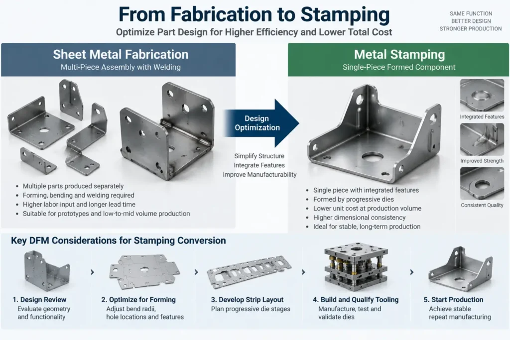
Signs a Part Is Ready for Dedicated Tooling
Procurement teams and engineering managers should consider converting a fabricated component to metal stamping when the following operational indicators align:
- Stable Design Freeze: The component drawing has reached design maturity, with minimal risk of near-term dimensional or feature changes.
- Capacity Constraints on Fabrication Machinery: Production demand creates bottlenecks on CNC laser cutters or press brakes, requiring excessive machine hours or line shifts to maintain supply.
- Cost-Reduction Mandates: High touch-labor content in press brake bending, secondary deburring, or manual welding limits piece-part cost-reduction goals.
- Strict Dimensional Consistency Requirements: Assembled components demand tighter part-to-part consistency to facilitate automated downstream robotic assembly lines.
DFM Changes Required Before Stamping Conversion
Directly converting a CAD drawing designed for sheet metal fabrication into a stamping die layout without redesign often leads to unnecessary tooling cost or process failure. The geometry must be optimized for continuous press operations:
- Optimizing Strip Yield and Grain Orientation: Features should be evaluated relative to continuous coil stock width and material grain direction. Aligning major bend lines perpendicular or diagonal to the material rolling direction prevents edge cracking during high-speed forming.
- Adjusting Bend Radii and Relief Slots: Press brake air-bending allows generous, flexible bend radii. Stamping tools rely on punch radius contours; bend radii must be standardized across the part to simplify die stations, and adequate bend relief notches must be incorporated to prevent material tearing along flanged edges.
- Redesigning Multi-Piece Welded Assemblies into Single Stampings: Fabricated structures often use multiple bent sheet sub-components spot-welded together to clear press brake tool limits. Stamping allows these features to be consolidated into a single drawn, bent, and formed stamped component with integrated stiffening ribs, eliminating secondary welding, fixtures, and assembly labor.
- Standardizing Hole Diameters and Feature Clearances: Pierced hole diameters in stamping should generally equal or exceed the material thickness to preserve punch tool steel life and prevent premature punch breakage. Distances from pierced holes to bend lines must be verified to prevent hole distortion during subsequent forming stations.
Managing Tool Qualification and Production Transition
Transitioning a component from fabrication to stamping involves an overlapping qualification period to ensure supply chain continuity:
- Prototype and Bridge Tooling Strategy: While permanent production dies are under construction, the existing sheet metal fabrication route remains active. Fabrication acts as bridge capacity to supply production lines during tool build-up and tryouts.
- First Article Inspection (FAI) and PPAP: Hardened die sets undergo rigorous tryouts, material springback adjustments, and dimensional study. A formal Production Part Approval Process (PPAP) or First Article Inspection verifies that stamped components meet all drawing specifications, geometric dimensioning and tolerancing (GD&T) callouts, and material property criteria.
- Design Cutover and Tooling Amortization: Once the stamping process achieves formal quality sign-off, volume production transfers entirely to the press line, and the fabrication line is decommissioned or reserved for low-volume spare parts support.
How OEM Buyers Should Choose Between Stamping and Fabrication
To select the correct manufacturing route for a custom metal component, OEM procurement officers and design engineers should systematically work through a structured decision framework:
| Question | Choose Metal Stamping When | Choose Sheet Metal Fabrication When |
|---|---|---|
| Production Volume | Annual demand is stable and high | Demand is low or uncertain |
| Design Status | Drawing is frozen and production-ready | Design changes are still expected |
| Geometry | Complex formed features are required | Flat profiles and simple bends are sufficient |
| Investment | Tooling investment can be amortized | Avoiding upfront capital is important |
| Timeline | Program allows tooling development | Fast prototype or launch is required |
- Assess Program Volume and Lifecycle Expectations: Calculate total lifetime production requirements, taking into account product launch curves, annual demand, service part needs, and expected program duration. Evaluate whether the projected lifecycle volume supports amortizing dedicated tooling NRE capital.
- Evaluate Design Maturity and Revision Risk: Determine the likelihood of upcoming engineering change orders (ECOs). If the product design is subject to ongoing customer modifications, field trial adjustments, or line variations, flexible sheet metal fabrication avoids the high cost and schedule delays of modifying hardened tool steel dies.
- Analyze Geometry and Forming Requirements: Review drawing features for complex three-dimensional contours, deep-drawn geometry, stiffening beads, coined surfaces, or multiple close-proximity formed tabs. Features that are slow or impractical to execute sequentially on press brakes strongly favor dedicated metal stamping.
- Establish Material and Tolerancing Specifications: Identify material grade, sheet thickness, temper, and required drawing tolerances. Evaluate whether critical dimensions are best maintained through high-repeatability die-hardened tool steel punches or flexible CNC machine positioning.
- Map Complete Manufacturing Route Costs: Compare the complete manufacturing route for both options rather than looking solely at raw forming cycles. Include secondary deburring, manual press brake handling, hardware insertion, secondary spot-welding, and downstream finishing.
- Evaluate Lead Time and Capital Commitment Horizons: Review project timeline constraints. If production parts are required within days or weeks, sheet metal fabrication provides rapid time-to-market. If project timelines allow for die design, wire-EDM tooling construction, and PPAP qualification, metal stamping provides a scalable high-speed production foundation.
Frequently Asked Questions
1. Is metal stamping a type of sheet metal fabrication?
Yes. Metal stamping is a specialized, tool-dedicated manufacturing method contained within the broader category of sheet metal manufacturing. While general sheet metal fabrication relies on flexible CNC machinery like lasers and press brakes to cut and form sheet metal sequentially, metal stamping uses dedicated die sets mounted in mechanical or hydraulic presses to perform shearing, punching, bending, and forming operations simultaneously or in rapid progression.
2. When is metal stamping more suitable than sheet metal fabrication?
Metal stamping is generally more suitable when a program features a mature, stable part design, consistent production demand over an extended program lifecycle, or complex three-dimensional formed features such as deep-drawn cups, stiffening beads, and coined details. Under these conditions, the higher initial investment in dedicated tooling is offset by significantly faster cycle times, lower touch-labor content, and lower piece-part costs.
3. Is sheet metal fabrication better for prototypes?
Yes. Sheet metal fabrication is usually the practical method for producing prototype components, initial design validations, and low-volume pre-production builds. Because fabrication utilizes standard CNC machinery, standard press brake V-dies, and software-driven laser cutting profiles, prototype parts can be manufactured quickly and economically without investing time or capital in dedicated press tooling.
4. Can a fabricated sheet metal part be converted to stamping?
Yes. Converting a component from sheet metal fabrication to progressive or transfer metal stamping is a common cost-reduction and scaling path as production demand grows. Successful conversion requires a Design for Manufacturability (DFM) review to adjust bend radii, optimize strip layout yield, standardize hole clearances, and adapt part features to high-speed die-forming operations. In many cases, multi-piece welded fabrication assemblies can be consolidated into a single stamped component.
5. How do tooling costs affect the choice between stamping and fabrication?
Tooling costs act as the primary financial divider between the two approaches. Sheet metal fabrication incurs low setup and programming costs because it uses universal machinery and standard tooling, making it economical for low volumes or evolving designs. Metal stamping requires substantial upfront Non-Recurring Engineering (NRE) investment for custom-engineered hardened steel dies. This capital investment must be justified by the expected production demand, lifecycle economics, and program requirements.
Conclusion
Choosing between metal stamping and sheet metal fabrication requires evaluating design maturity, geometric complexity, material yield, tooling capital, and total lifecycle program economics rather than relying on fixed volume thresholds or universal process preferences.
Sheet metal fabrication provides exceptional agility, minimal upfront setup costs, and fast delivery, making it a practical choice for prototypes, low-to-mid volume production, evolving designs, and highly customized product variants. Metal stamping can provide significantly higher production speed, high process repeatability, low labor content per unit, and the ability to form complex 3D features, making it a compelling choice for high-volume, mature production programs where upfront tooling capital can be amortized effectively.
By systematically applying a complete manufacturing route comparison—evaluating initial NRE against piece-part economics and design flexibility—OEM engineers and procurement teams can select the appropriate manufacturing strategy that optimizes both component quality and program profitability. For OEM projects considering the transition from sheet metal fabrication to metal stamping, a DFM review based on the actual drawing and production requirements can help determine the appropriate manufacturing route.
Pingback: What is Metal Stamping? A Complete Guide — Metal Stamp Factory