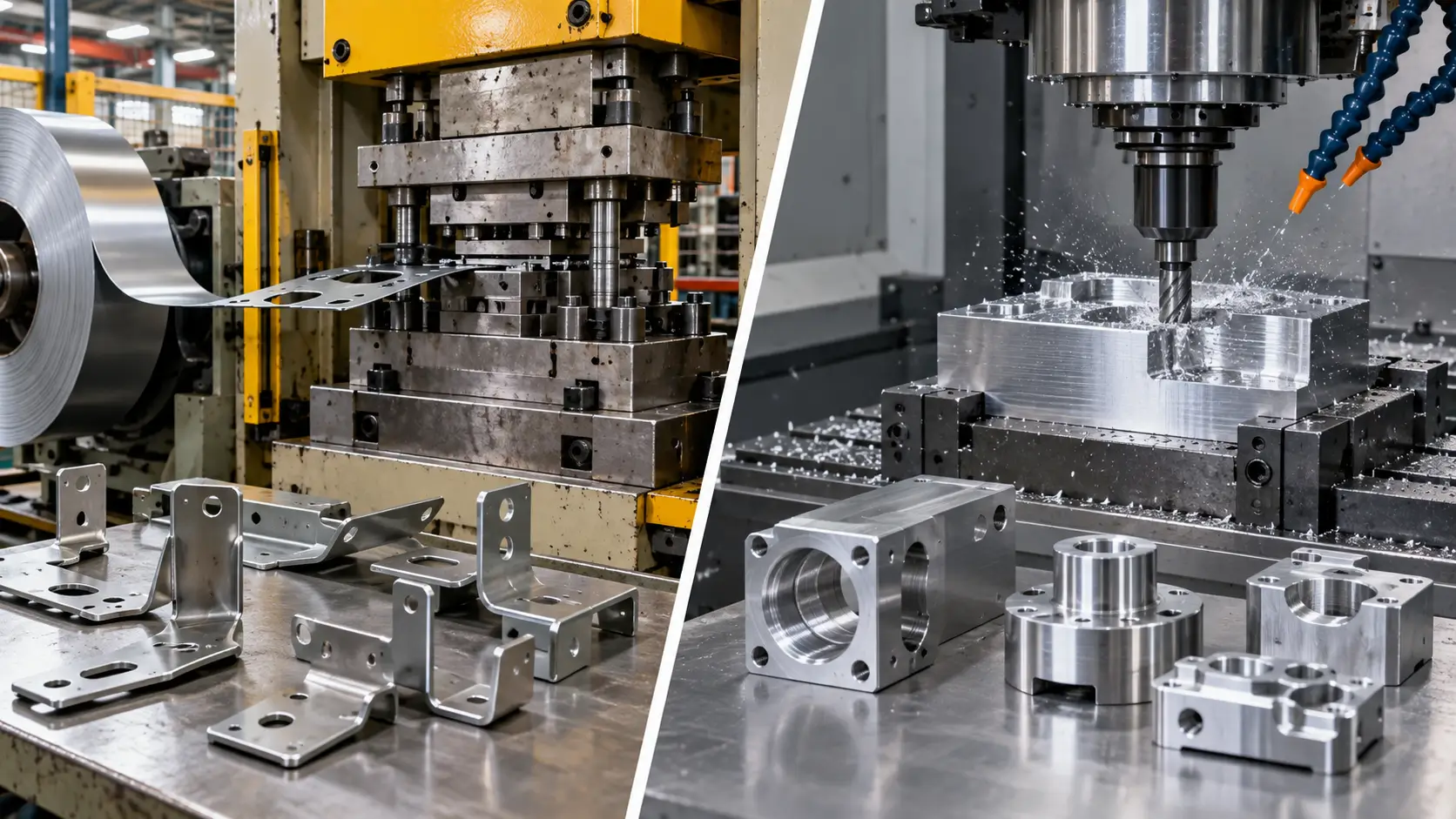
In precision metal stamping, establishing clear burr requirements is critical for part function, safe handling, downstream assembly, and manufacturing cost. A common question among OEM engineers and procurement professionals is whether a single, universal metal stamping burr tolerance exists for all stamped components.
The short answer is no. Acceptable burr levels vary widely based on material selection, sheet thickness, part application, edge location, and subsequent processing steps. Assuming a single rule applies to every stamped part can lead to over-specifying requirements, which increases tooling and deburring costs, or under-specifying them, which risks assembly interference, potential damage to nearby insulation or electrical components, or installation hazards.
This guide explains how burrs form during the sheet metal cutting process, how to distinguish standard edge characteristics from quality defects, how to evaluate edge requirements on engineering drawings, and how custom stamping manufacturers inspect and control burrs during high-volume production.
What Is Burr in Metal Stamping?
In metal stamping, a burr is a thin, raised ridge or sliver of material that remains along the edge of a part after a shearing, punching, blanking, or piercing operation. It forms on the exit side of the cutting tool as the material transitions from plastic deformation to ultimate tensile fracture.
To evaluate burr height and determine appropriate edge quality specifications, engineers must first understand the anatomy of a stamped cut edge.
Rollover, Burnished Zone, Fracture Zone, and Burr
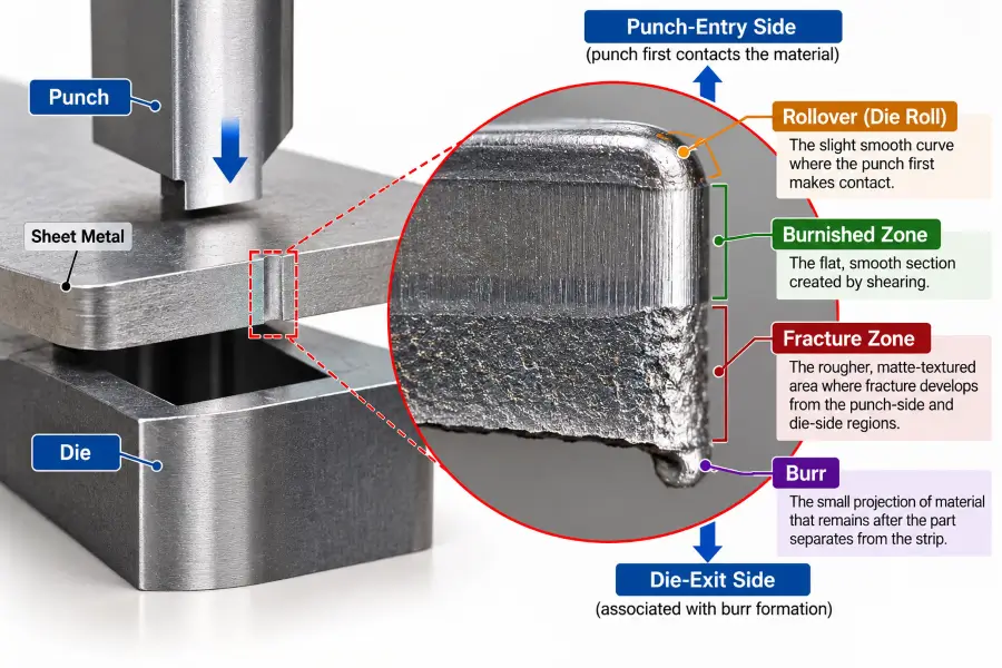
When a punch impacts a sheet of metal supported by a die, the material progresses through physical stages that result in four recognized cut-edge zones:
- Rollover (Die Roll): The slight smooth curve on the surface where the punch first makes contact. As the tool presses into the sheet, the material deforms plastically and rolls into the cut zone before shearing begins.
- Burnished Zone (Shear Band): The flat section directly adjacent to the rollover zone. This is created as the cutting edge of the punch penetrates the material and shears through a portion of its thickness.
- Fracture Zone (Cut Band): The rougher, matte-textured area beyond the burnished zone. As penetration continues, fracture develops from the punch-side and die-side regions. With an appropriate clearance for the material and thickness, the fracture paths can align to produce a more consistent cut edge.
- Burr: The small projection of material located at the edge of the fracture zone. It represents the final material that stretched and tore as the component separated from the strip.
Punch-Entry Side vs. Die-Exit Side
A stamped edge is asymmetrical:
- Punch-Entry Side: The side where the punch first contacts the material. It typically shows edge rollover and the beginning of the burnished zone.
- Die-Exit Side: The side facing the die cavity as the punch completes its stroke. It is associated with the end of the fracture zone and burr formation.
Because burr formation is typically associated with the die-exit side in conventional blanking and piercing, edge orientation can be just as important as burr height. Knowing which side of the component contains the burr allows product designers to consider its orientation relative to mating surfaces, wire harnesses, or operator contact zones.
Is There a Standard Metal Stamping Burr Tolerance?
Engineering teams often search for an overarching industry standard that defines allowable burr limits for all sheet metal parts. In practice, no single universal numerical burr limit governs every stamped component across all industries.
Applying an arbitrary limit across all drawings can be problematic:
- Part Function Varies: A structural mounting bracket mounted in an unexposed enclosure does not require the same tight edge specification as a high-precision electrical terminal or a dynamic sealing flange.
- Material Thickness Matters: A fixed expectation that works reasonably well for thin gauge metals may produce an unacceptably large burr if applied directly to thick plate stampings.
- Cost Constraints: Requesting a near-zero burr across an entire component contour often requires secondary processing or tighter tooling maintenance cycles, which increases piece price and tooling investment.
Instead of relying on assumed rules of thumb, engineers should establish edge specifications within the broader framework of metal stamping tolerances, while evaluating customer drawing requirements, functional assembly needs, material behavior, and the capability of the stamping process.
What Determines Acceptable Burr Height?
Determining whether a burr is acceptable requires evaluating how the component interacts with other parts, human operators, and its operating environment.
| Factor | Why It Matters | Specification Consideration |
|---|---|---|
| Part Function | High-frequency or high-stress parts can experience stress concentrations at rough burr locations. | Identify stress-critical features and evaluate burr limits on high-fatigue edges. |
| Assembly Fit | A burr on a locating edge or datum surface can cause misalignments during secondary assembly. | Evaluate edge limits on mating faces or orient burrs away from contact zones. |
| Operator Handling | Sharp burrs along external contours pose cut risks to assembly line workers or end users. | Consider a defined edge condition, burr limit, or suitable deburring requirement on exposed edges. |
| Electrical Contact | Loose or excessive burrs in electrical enclosures can increase the risk of short circuits or chafe wire insulation. | Evaluate maximum allowable burr limits or deburring requirements on conductive parts. |
| Sealing Surfaces | Burrs on fluid or gas sealing flanges can prevent gaskets from seating flat, increasing leak risks. | Define an edge condition appropriate for the sealing interface. |
| Plating and Coating | High burrs can cause localized high-current density during plating, potentially leading to uneven build-up. | Evaluate edge projections prior to secondary surface finishing. |
| Material and Thickness | Tensile strength, ductility, and stock thickness influence fracture behavior and edge geometry. | Tailor expectations to the specific material grade and sheet thickness. |
| Edge Location | Internal functional cutouts may require strict limits, while external non-mating profiles can tolerate larger edges. | Consider zoned edge specifications on drawings rather than blanket title-block notes. |
What Causes Excessive Burr Height in Metal Stamping?
In a progressive or single-station stamping die, burr height is influenced by the interaction between the cutting tools, press conditions, process setup, and raw stock. When burr height increases beyond acceptable limits, it can indicate that one or more of these conditions should be investigated.
| Observation | Possible Cause | Engineering Check / Response |
|---|---|---|
| Uniformly excessive burrs along the cut edge, accompanied by secondary shear or heavy rollover. | Improper Tool Clearance | Re-evaluate punch-to-die clearance based on material type and thickness. |
| Gradually increasing burr height over a production run, accompanied by a rounded edge on the tool. | Tool Wear and Dulling | Inspect tool condition and determine whether sharpening or repair is required. |
| Uneven burr height around the perimeter of a single feature. | Punch/Die Misalignment | Inspect punch guides and related guiding components for possible alignment shifts. |
| Localized, tall, jagged burr peaks matching specific locations on the tool profile. | Chipped Cutting Edges | Inspect tool edges to assess possible localized damage and determine whether repair is required. |
| Changes in burr characteristics between different material coils or lots. | Material Variation | Verify relevant material properties and temper against the applicable material documentation. |
| Burr condition varies during production even when material and nominal clearance remain unchanged. | Press or Tooling Stability | Check press setup, tooling alignment, die support, and other conditions that may affect cutting consistency. |
How Punch-to-Die Clearance Affects Burr Formation
Punch-to-die clearance is the gap between the punch cutting edge and the die cutting edge on each side of the cut. It is a critical variable controlling cut-edge quality.
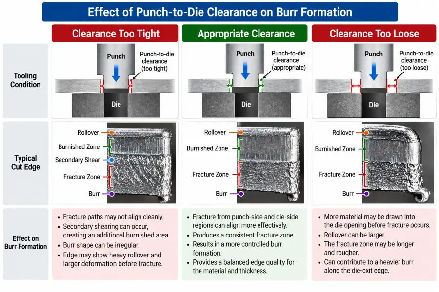
When clearance is appropriate for a given material and thickness, fracture from the punch-side and die-side regions can align more effectively, helping produce a more consistent fracture zone and controlled burr formation.
- Clearance Too Tight: Fracture paths from the punch and die regions may not align cleanly. Secondary shearing can occur, creating an additional burnished area and potentially contributing to an irregular burr.
- Clearance Too Loose: More material may be drawn into the die opening before fracture occurs, which can increase rollover and contribute to a heavier burr along the die-exit edge.
Clearance selection depends on material properties, thickness, and part requirements. No single clearance percentage applies to all alloys or applications.
How Tool Wear Changes Burr Height During Production
Even with appropriate initial tool clearance, cutting tools experience wear during production runs. As the sharp edges of the punch and die buttons wear down, their cutting behavior changes.
Instead of separating the sheet under the same cutting conditions as a sharp tool, worn cutting edges may allow greater deformation before fracture occurs. As cutting edges wear, burr height may increase and can serve as one practical indicator that tooling condition should be checked.
Monitoring edge condition over time helps maintain process control. However, increasing burr height alone does not automatically prove tool wear, as material lot variations, clearance changes, press stability, or alignment shifts can also affect edge formation.
Factory Case: Burr Control in High-Volume SUS304 Bird Spike Production
To illustrate how burr requirements are managed during continuous manufacturing, consider a high-volume stamping application producing an OEM stainless steel component.
- Product: Stainless steel bird spike base
- Material: SUS304 stainless steel
- Production Volume: Approximately 100,000 pieces per month
- Manufacturing Method: Progressive die stamping
- Tooling Note: The progressive die tooling was manufactured using wire EDM
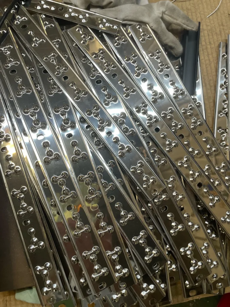
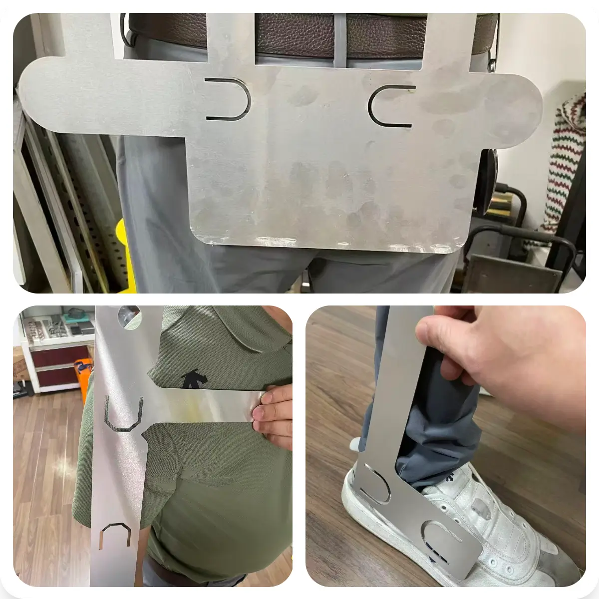
Under normal production conditions, the two bottom edges of the base are controlled so that they do not have sharp burrs that could scratch workers during installation.
To maintain edge safety across high monthly volumes, the following workflow is executed:
- Sampling Inspection: Quality inspectors perform sampling inspection during high-volume production.
- Production Stop: If burrs are found on both edges during sampling inspection, production is stopped immediately.
- Tool Inspection and Repair: The stamping die is inspected and repaired as necessary.
- Manual Deburring: Parts already produced with unacceptable burrs are manually deburred by workers using a scraper.
- Safe Handling Verification: After deburring, the edges are checked so they will not scratch the hand during handling and installation.
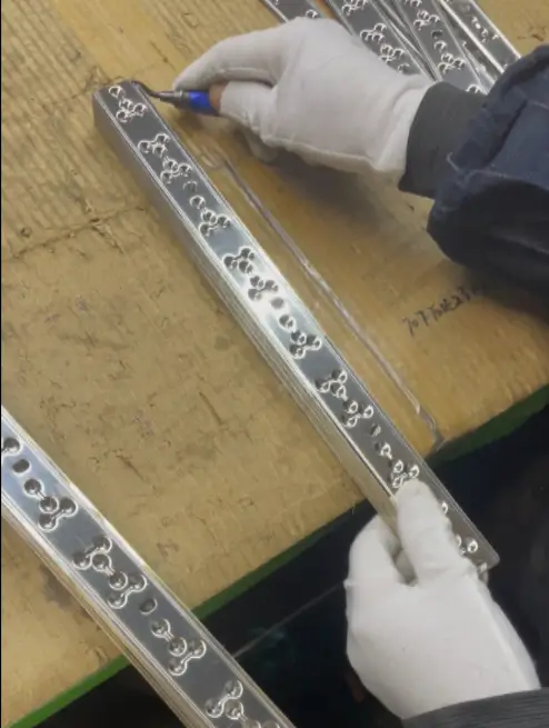
This case shows how a functional edge requirement can lead to sampling inspection, production stoppage, tool inspection and repair, and manual deburring of affected parts.
Why Burr Direction Matters in OEM Parts
In many engineered components, the direction in which a burr points can be as important as the height of the burr itself. Because burr formation is typically associated with the die-exit side in conventional blanking and piercing, evaluating edge orientation during design can reduce the risk of functional issues and may reduce the need for additional edge processing.
Key engineering considerations for burr direction include:
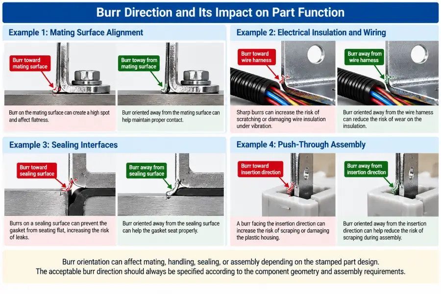
- Mating Surface Alignment: If a stamped face must mount flush against a flat mating plate, orienting the die-exit side away from the contact face may help avoid high spots that tilt the assembly out of parallel.
- Electrical Insulation and Wiring: When stamped metal brackets sit near wire harnesses, orienting the burr direction away from the wires can reduce the risk of sharp edges wearing through cable insulation under vibration.
- Sealing Interfaces: On fluid manifolds or cover plates using elastomeric seals, facing the burr away from the seal can reduce the risk of cutting the rubber during compression.
- Push-Through Assembly: For tabs or connectors pushed into plastic housings, burr orientation should be evaluated based on the assembly sequence to reduce the risk of scraping material into sensitive areas.
Acceptable burr orientation should always be evaluated based on the specific component geometry and assembly environment.
How Should Burr Requirements Be Specified on an Engineering Drawing?
For broader drawing-level requirements beyond burr and edge callouts, see our guide to stamped part drawing notes.
Vague annotations on technical drawings often lead to misunderstandings between OEM purchasing teams and contract manufacturers.
General callouts such as "REMOVE ALL BURRS" or "NO BURRS ALLOWED" can be ambiguous. From a practical manufacturing perspective, mechanical cutting processes naturally leave micro-level edge features. Unclear wording may lead suppliers to quote manual deburring operations that are functionally unnecessary, or assume an as-stamped edge condition that fails during assembly.
To create clear, enforceable drawing specifications, engineers should consider specifying:
- Affected Edges: Indicate which edges are function-critical and require strict limits, and which non-mating profiles can accept an as-stamped edge condition appropriate for the application.
- Maximum Burr Requirement: Define an explicit maximum allowable burr dimension where function, assembly, handling, or acceptance requirements justify a quantitative limit. Not every stamped part requires a numerical maximum burr height.
- Burr Direction: Clarify acceptable burr orientation relative to assembly datum faces where relevant.
- Edge Condition: Specify permissible edge breaks or radii where sharp corners present handling or assembly concerns.
- Inspection and Acceptance Method: Clarify how edge compliance will be evaluated during receiving inspection when necessary.
ISO 13715 and Edge Specifications
ISO 13715 provides a standardized framework for indicating and dimensioning edges of undefined shape on technical drawings. It can be relevant when a drawing needs to communicate permitted material excess or removal at an edge.
However, ISO 13715 does not establish one universal allowable burr height for stamped parts. The actual acceptance requirement still needs to be defined for the component and its function.
How Is Burr Height Measured on Stamped Parts?
Accurate measurement is essential for verifying compliance with drawing specifications. Depending on whether the requirement is qualitative or quantitative, different inspection methods may be applied.
For the broader stamped-part inspection and acceptance workflow, including dimensional checks, FAI, sampling, reporting, and nonconformance handling, see our metal stamping quality inspection guide.
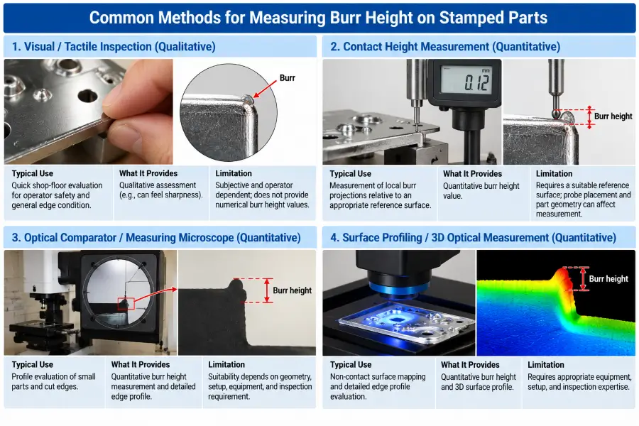
| Inspection Method | Quantitative or Qualitative | Best Use | Limitation |
|---|---|---|---|
| Visual / Tactile Inspection | Qualitative | Quick shop-floor evaluation for operator safety and general edge condition. | Subjective and operator dependent; does not provide numerical burr height values. |
| Contact Height Measurement | Quantitative | Measurement of local burr projections relative to an appropriate reference surface using contact-based equipment. | Requires a suitable reference surface; probe placement and part geometry can affect measurement. |
| Optical Comparator / Measuring Microscope | Quantitative | Profile evaluation of small parts and cut edges. | Suitability depends on geometry, setup, equipment, and inspection requirement. |
| Surface Profiling / 3D Optical Measurement | Quantitative | Non-contact surface mapping and detailed edge profile evaluation. | Requires appropriate equipment, setup, and inspection expertise. |
The measurement method should therefore be selected according to the geometry of the feature, the required acceptance criterion, and the level of quantitative verification needed.
Burr Inspection During Production
In high-volume custom metal stamping, managing edge quality relies on practical process controls rather than relying solely on final sorting. A general burr-control workflow in a stamping operation may include:
- First-Piece Edge Evaluation: Initial samples from a press setup may be checked for edge condition and burr orientation before the production run proceeds.
- In-Process Sampling: Operators or quality personnel may pull sample parts during the run to check edge condition where required.
- Observation of Burr Changes: Changes in edge condition can help indicate potential shifts in setup, material, or tool condition.
- Tooling Feedback: When burr condition approaches or exceeds drawing limits, tooling or production personnel can inspect the process and die condition.
- Final Acceptance: Parts are accepted according to the applicable engineering drawing or agreed customer quality requirements.
The exact inspection frequency and acceptance method should be determined by the part requirements and the applicable quality plan rather than assumed from a universal stamping rule.
How to Control Burrs at the Stamping Die
Preventing excessive burr formation at the press is generally more practical than relying on post-stamping secondary processing. Several core tooling and process controls can influence burr formation:
- Appropriate Punch-to-Die Clearance: Match punch-to-die clearance to the specific material grade, temper, sheet thickness, and application.
- Cutting-Edge Condition: Monitor the condition of punch and die cutting edges as production continues.
- Punch/Die Alignment: Maintain appropriate alignment between punch and die components so that cutting clearance remains consistent around the feature.
- Die Maintenance: Inspect tooling when edge quality changes and perform sharpening or repair when tool condition indicates it is necessary.
- Process Monitoring: Monitor press setup, strip feeding, material consistency, and other relevant production conditions.
The objective is not necessarily to eliminate every microscopic edge projection, but to maintain an edge condition that meets the drawing and functional requirements of the part.
When Is Secondary Deburring Necessary?
Secondary deburring may be necessary when the as-stamped edge condition cannot meet functional, handling, assembly, or drawing requirements.
Because secondary processing adds handling steps and manufacturing cost, method selection depends on part geometry, edge requirements, material, production volume, dimensional sensitivity, and downstream requirements.
- Vibratory Finishing / Tumbling: Uses abrasive media and vibratory motion to treat exposed edges on suitable parts.
- Barrel Finishing: Uses tumbling action with media and may be suitable for components that can tolerate part-to-part contact.
- Belt Grinding / Brush Conditioning: Can be used to treat accessible edges and flat profiles.
- Manual Deburring: Scraping, filing, or other manual edge treatment can be used for localized features, low-volume work, or rework of affected production parts.
The appropriate method should be selected according to the required edge condition without unnecessarily affecting functional dimensions or other part features.
OEM Burr Specification Checklist
When preparing drawings or issuing a Request for Quotation (RFQ) for custom metal stampings, engineering and sourcing teams can use this checklist to clarify edge requirements:
| Checklist Item | Engineering Question |
|---|---|
| Critical Edges | Which specific edges are function-critical versus non-critical? |
| Burr Requirement | Is a quantitative maximum burr height necessary, or is an agreed as-stamped edge condition acceptable? |
| Burr Direction | Does burr orientation matter relative to assembly or mating surfaces? |
| Operator Handling | Will workers or end users handle the edge directly? |
| Electrical / Sealing Interface | Could the edge interact with wire insulation, electrical components, or sealing elements? |
| Secondary Deburring | Is secondary deburring required, or can the part be accepted in its as-stamped condition? |
| Inspection Method | How will edge compliance be evaluated during inspection and acceptance? |
Frequently Asked Questions About Metal Stamping Burr Tolerance
What is an acceptable burr height for a stamped part?
There is no single universal acceptable burr height for every stamped part. The appropriate limit depends on part function, material, thickness, edge location, engineering drawing requirements, assembly conditions, handling requirements, manufacturing capability, and agreed acceptance criteria.
Does ISO 13715 specify a maximum burr height for metal stamping?
No. ISO 13715 provides a standardized framework for indicating and dimensioning edges of undefined shape on technical drawings, but it does not establish one universal maximum burr height for all stamped parts. The specific requirement must be defined on the engineering drawing or through agreed acceptance criteria.
What is the difference between a burr and flash in manufacturing?
A burr is a small ridge or projection of material associated with cutting operations such as shearing, punching, or blanking. Flash generally refers to excess material formed at parting or interface regions in processes such as casting, molding, or forging.
How does material affect stamping burr formation?
Factors such as tensile strength, ductility, temper, stock thickness, and fracture behavior influence how metal deforms and separates during cutting. Material behavior must be considered together with punch-to-die clearance, cutting-edge condition, alignment, and other process conditions rather than assuming a simple rule based on whether a material is soft or hard.
Can wire EDM eliminate burrs during progressive die stamping?
No. Wire EDM is a tool-making method used to manufacture precision die components. It can support precise tooling geometry, but it does not eliminate burr formation during stamping production. Burr condition can change as cutting edges wear or as material, alignment, and other process conditions vary.
Get an Engineering Review for Your Stamped Part
Managing edge quality and burr specifications effectively requires balancing part functionality with practical manufacturing capabilities.
If you are developing a new stamped component or reviewing existing technical drawings, our engineering team can evaluate your specifications to help align edge quality requirements, tooling considerations, and production efficiency.
Submit your part drawings, material specifications, material thickness, estimated annual volume, and critical edge requirements for a technical review and custom manufacturing quote.