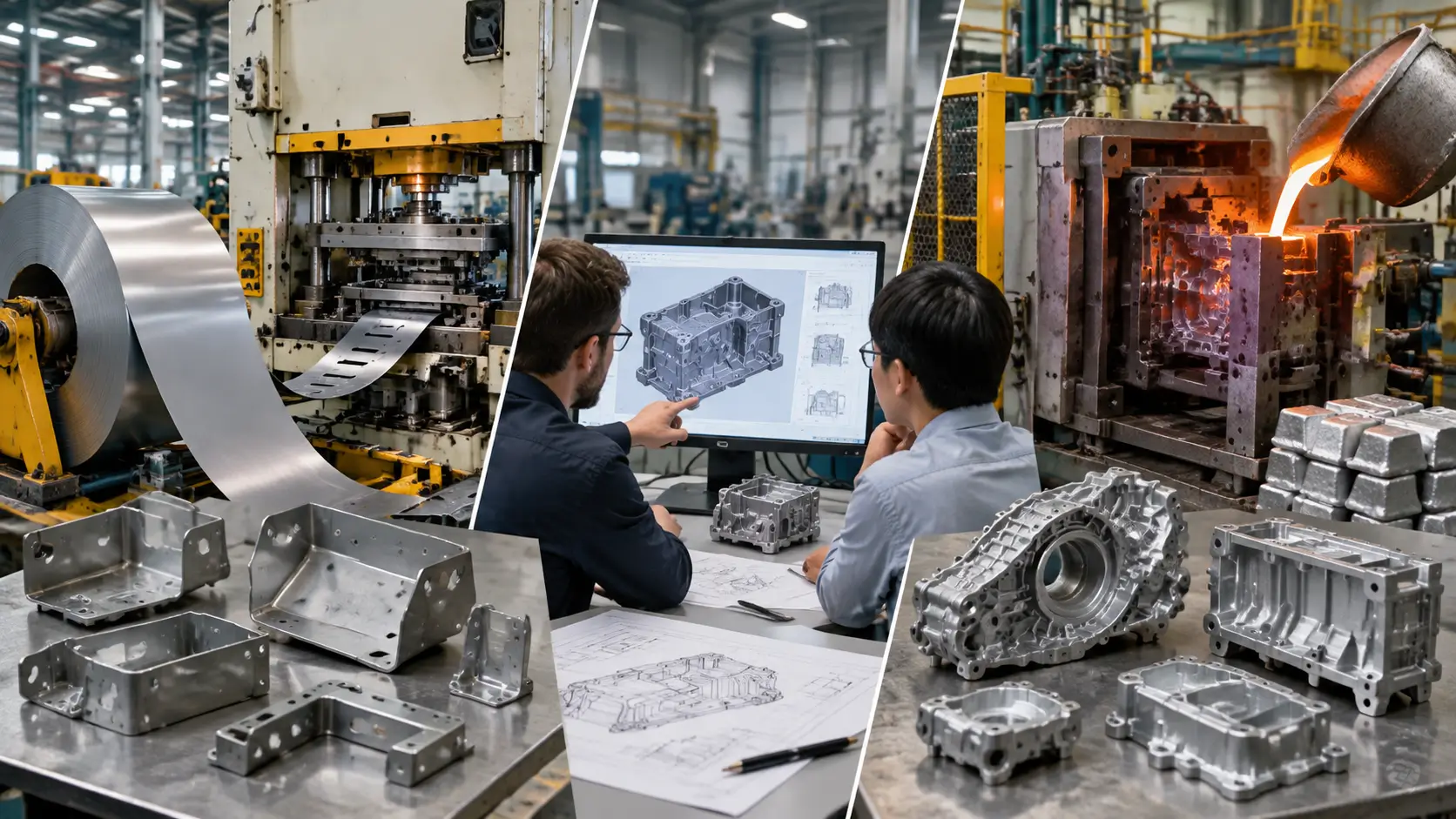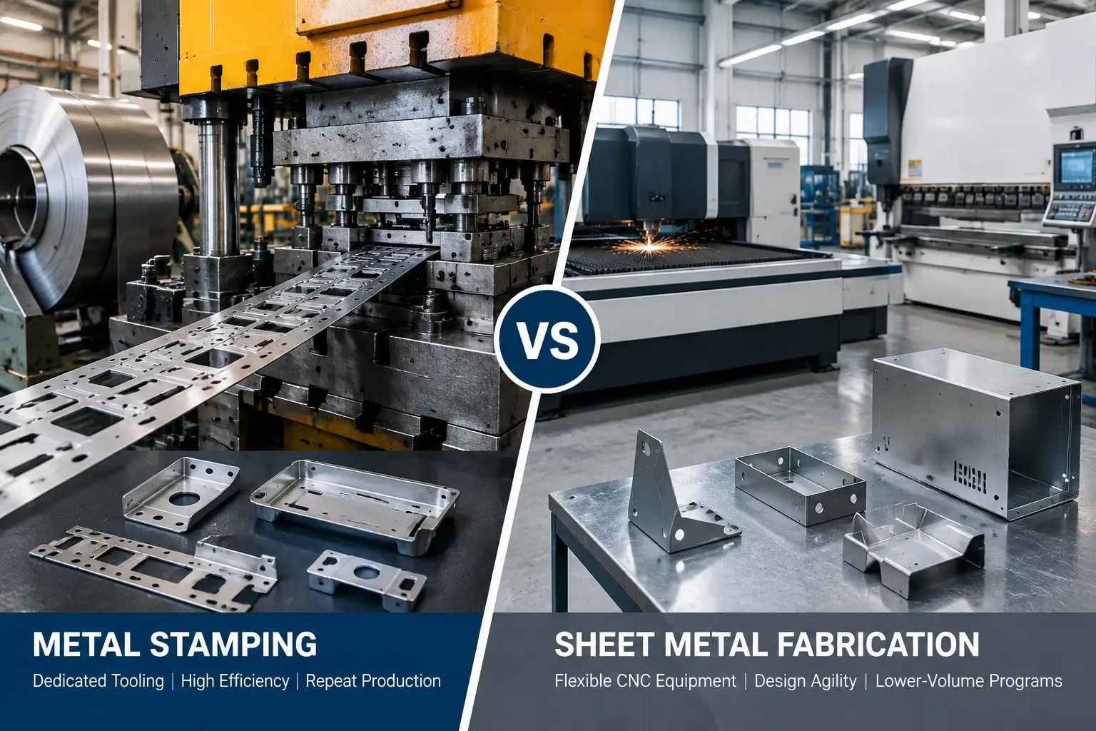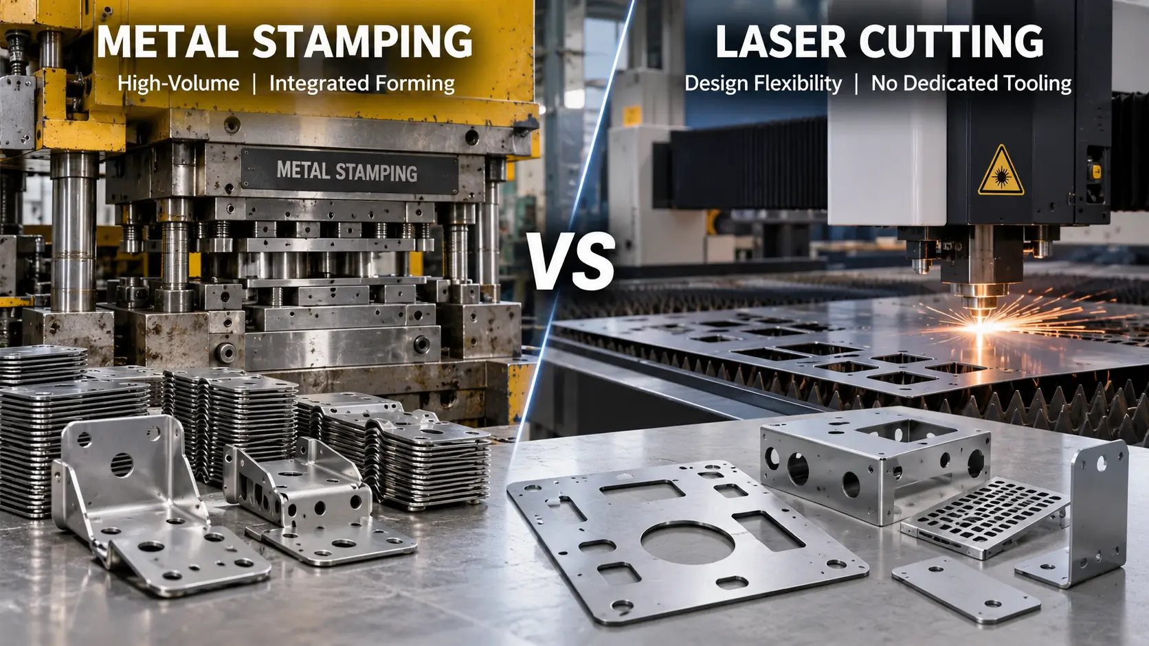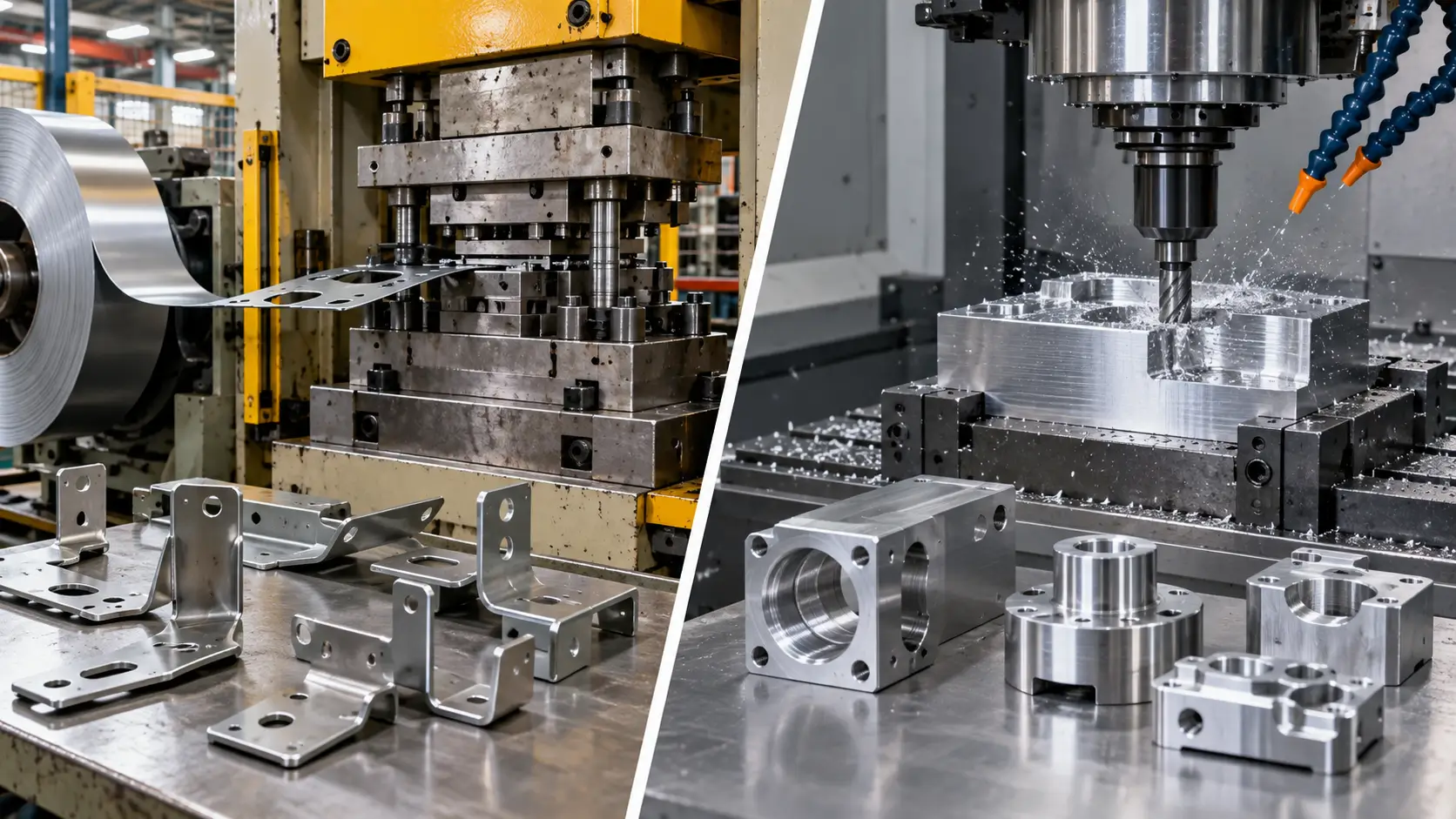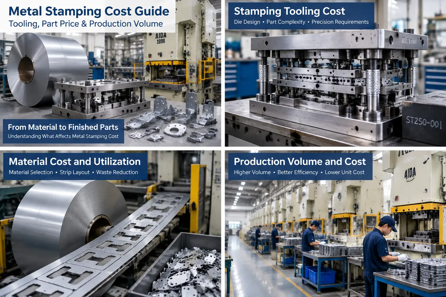
Navigating stamping die selection requires balancing technical part specifications against overall manufacturing goals. Evaluating a project is rarely as simple as picking a die category from a catalog. A tooling direction that appears suitable from part geometry alone may change once material, thickness, tolerance, production requirements, and other manufacturing constraints are considered.
Evaluating part features, material properties, tolerance expectations, production volume, and tooling investment together helps identify a practical tooling direction. DFM validation helps determine whether the preliminary tooling direction is practical for the part and manufacturing requirements before the tooling strategy is finalized.
Quick Guide: How Stamping Die Selection Works
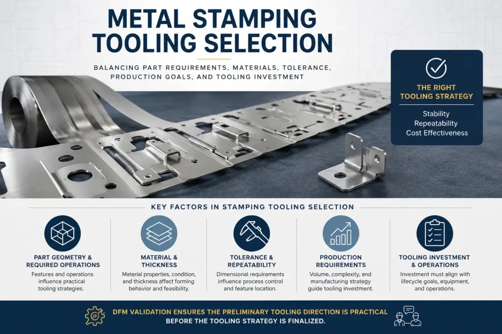
Stamping die selection is a multi-variable engineering evaluation rather than a single calculation. No individual project factor dictates the entire tooling choice; instead, engineers and procurement teams evaluate several interdependent variables:
- Part Geometry and Required Operations: Part geometry and required operations influence which tooling strategies are practical.
- Material Characteristics and Thickness: Material properties, condition, and thickness affect forming behavior and tooling feasibility.
- Tolerance and Repeatability: Tolerance and repeatability requirements affect how tooling strategy and process-control requirements should be evaluated.
- Production Requirements and Tooling Investment: Tooling investment should be evaluated together with production requirements, expected volume, part complexity, and manufacturing strategy.
Stamping Die Selection Quick Reference
| Evaluation Factor | Key Question | Impact on Tooling Selection |
|---|---|---|
| Part Geometry | What features and operations are required? | Determines cutting, bending, forming strategy |
| Material | What alloy, thickness, and behavior are involved? | Affects tooling feasibility and forming approach |
| Tolerance | Which dimensions are critical? | Influences locating and process control requirements |
| Production Volume | How stable is the demand? | Affects tooling investment decisions |
| Manufacturing Strategy | What automation or secondary operations are needed? | Influences overall process design |
Because these factors interact, a preliminary tooling strategy should be validated through DFM before the tooling direction is finalized.
Tooling Strategy Orientation: Common Stamping Die Options
Understanding the basic terminology used to describe metal stamping tooling is an important first step in the selection process. Stamping tooling strategies are generally grouped into four main operational categories:
- Single-Operation / Single-Hit Dies: Tooling designed to perform an individual stamping operation or standalone press stroke on a part.
- Compound Dies: Tooling engineered to perform multiple cutting-related operations within a single press stroke.
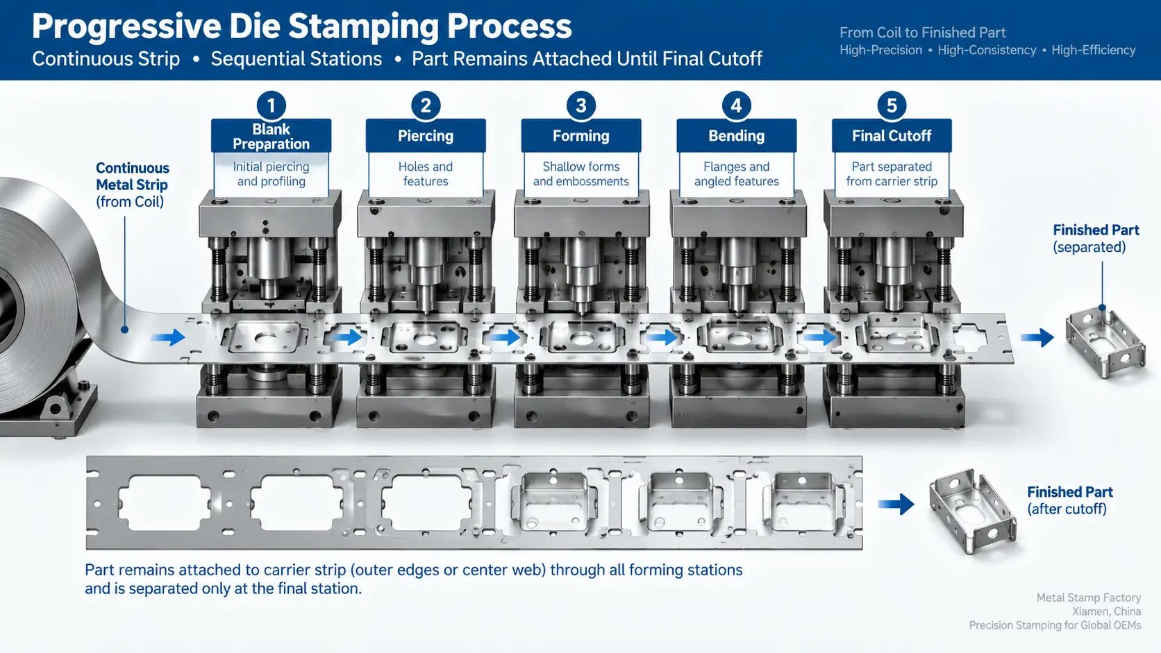
- Progressive Dies: Tooling arranged so that strip stock advances through sequential operations or stations before the final part is separated.
- Transfer Dies: Tooling setups where individual parts or pre-cut blanks are transferred between separate operations or stations.
These categories outline distinct methods for organizing operations within press equipment, but a category label alone does not determine the right choice for a project. Identifying a practical tooling strategy requires evaluating the specific part features, material behaviors, tolerance expectations, and production requirements detailed in the following sections.
Major Factors in Stamping Tooling Selection
Selecting the right tooling strategy requires evaluating a combination of technical, material, and commercial variables. No single feature dictates a tooling choice in isolation. Instead, engineering and procurement teams analyze how different requirements interact across the part lifecycle.
Factor A – Part Geometry and Required Operations
Part geometry and required operations influence which tooling strategies are practical. Features such as holes, slots, bends, formed tabs, draw depths, and external contours help define the forming and cutting operations that may need to be considered.
Simpler part geometries may require straightforward cutting or forming setups, whereas complex components with multiple bends or feature relationships require multi-stage processing. Engineers evaluate whether operations can be completed in a single press stroke, distributed across sequential die stations, or handled across separate operations. The spatial arrangement of features also influences how operations are sequenced to maintain dimensional integrity.
Factor B – Material Properties and Stock Thickness
Material properties, condition, and thickness affect forming behavior and tooling feasibility. Alloy characteristics, temper, tensile strength, and ductility influence how sheet metal responds to shear and forming forces during processing.
Stock thickness is another important consideration because it affects forming behavior and overall tooling feasibility. Material supply format, whether continuous coils, cut strips, or discrete blanks, can also influence how stock handling is evaluated within the tooling strategy.
Factor C – Tolerance and Repeatability Requirements
Tolerance and repeatability requirements affect how tooling strategy and process-control requirements should be evaluated. Critical feature-to-feature relationships, hole location tolerances, and overall dimensional expectations influence how part positioning is maintained during stamping.
When tight dimensional relationships must be preserved across multiple features, the tooling evaluation focuses on how consistently parts can be located and indexed. Multi-station tooling and standalone dies utilize different indexing and locating methods to manage feature placement. Tooling strategies must account for consistent material behavior across production runs to meet specified tolerances.
Factor D – Production Requirements, Volume and Tooling Investment
Tooling investment should be evaluated together with production requirements, expected volume, part complexity, and manufacturing strategy. Rather than applying fixed volume rules, manufacturing teams consider how initial tooling expenditure aligns with overall program needs.
For a detailed breakdown of how die type, tooling complexity, production volume, material, tolerances, and secondary operations influence project economics, see our metal stamping cost guide.
Supporting operational factors may also be considered during evaluation:
- Secondary operations required after stamping
- Possible integration of in-die operations
- Automation requirements where applicable
- Press and equipment compatibility
- Routine maintenance accessibility
Evaluating these supporting factors helps align capital investment with
broader manufacturing and operational strategies.
Summary of Major Die Selection Factors
| Factor | Main Consideration |
|---|---|
| Geometry | Operation sequence and feature relationships |
| Material | Forming behavior and tooling feasibility |
| Tolerance | Repeatability and feature positioning |
| Volume | Tooling investment and production strategy |
| Operations | Secondary processes and automation |
The 4-Stage Stamping Die Selection Framework
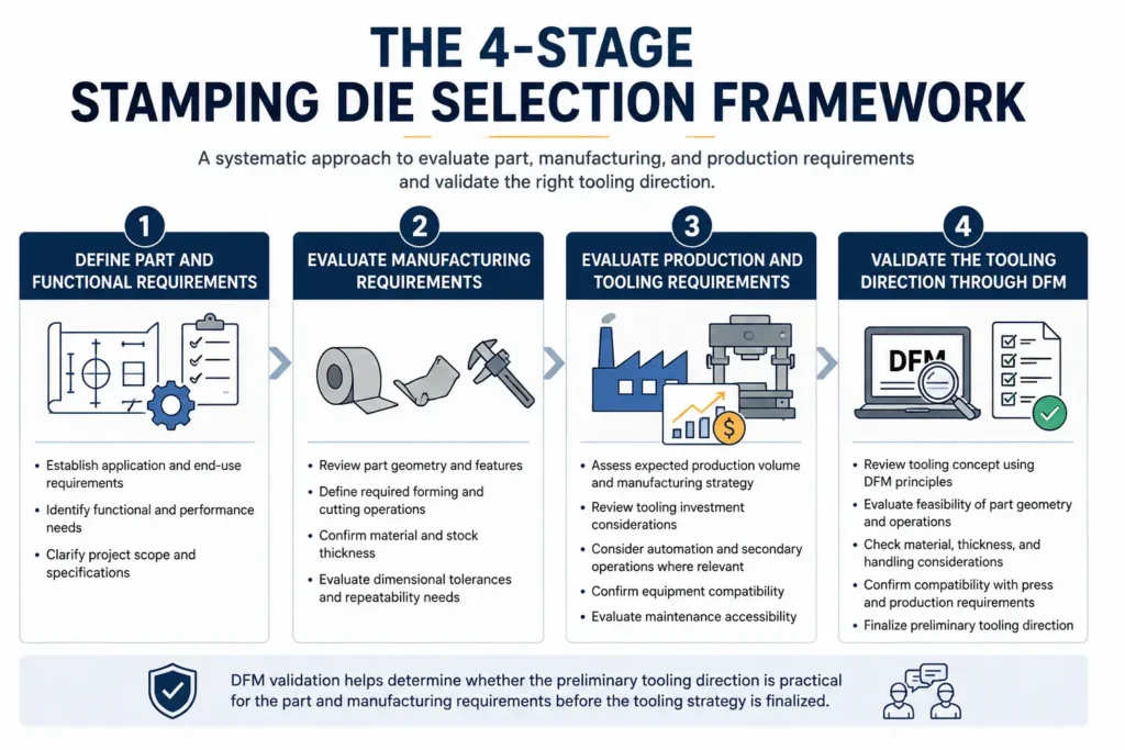
To arrive at a preliminary tooling decision, manufacturing teams can follow a systematic four-stage evaluation framework:
- Define Part and Functional Requirements: Establish core application demands, end-use specifications, functional requirements, and project scope.
- Evaluate Manufacturing Requirements: Analyze part geometry, required forming and cutting operations, material specifications, stock thickness, and dimensional tolerances.
- Evaluate Production and Tooling Requirements: Review anticipated production volume, manufacturing strategy, tooling investment considerations, relevant automation or secondary-operation needs, equipment compatibility, and maintenance accessibility.
- Validate the Tooling Direction Through DFM: Review the preliminary tooling strategy using Design for Manufacturability principles. DFM validation helps determine whether the preliminary tooling direction is practical for the part and manufacturing requirements before the tooling strategy is finalized.
Project-Centric Tooling Selection Matrix
The following matrix provides a conceptual overview of how common project conditions are evaluated during tooling selection. This table serves as an initial decision aid, as multiple variables must always be assessed in combination.
| Project Condition | Why It Matters | Tooling Considerations | Potential Tooling Direction |
|---|---|---|---|
| Flat geometry with important feature-to-feature relationships | Important feature relationships need to be considered when evaluating how operations will be organized. | Evaluate the required operations, tolerance relationships, and handling strategy together. | Evaluate tooling approaches capable of maintaining the required feature relationships; final direction depends on the complete part and process requirements. |
| Multiple forming operations required on coiled stock | Operation sequence and stock handling must be evaluated together. | Evaluate whether the part and required operations are compatible with continuous-strip processing. | Continuous-strip tooling may be evaluated if compatible with the complete part and operation requirements. |
| Formed part geometry where continuous-strip handling may be difficult | Part geometry and handling requirements may affect whether continuous-strip processing is practical. | Evaluate part handling and operation sequence during DFM. | Part-handling and transfer-based approaches may need evaluation during DFM. |
| Specialized post-process shape restoration or some lower-quantity production requirements | A targeted standalone operation may be appropriate for a specific manufacturing task. | Evaluate whether an individual operation can address the required task without assuming a multi-station solution. | Single-operation / single-hit tooling may be evaluated. |
| Electrical component with an elasticity requirement produced from continuous phosphor bronze strip | Material function and continuous-strip processing both need to be considered. | Evaluate whether the required operations are compatible with continuous-strip processing. | Progressive tooling may be considered when continuous-strip processing is suitable. |
| Component where secondary or in-die operations are being considered | Operation integration adds additional manufacturing and tooling considerations. | Evaluate whether the additional operation is compatible with the overall tooling and production strategy. | Evaluate whether operation integration is technically appropriate within the overall tooling strategy. |
Real Factory Evidence: Tooling Selection in Production
Real-world manufacturing observations demonstrate how tooling choices are adapted to specific production goals, part geometries, and processing tasks.
Case Study A – Single-Operation Tooling for Specialized Rework
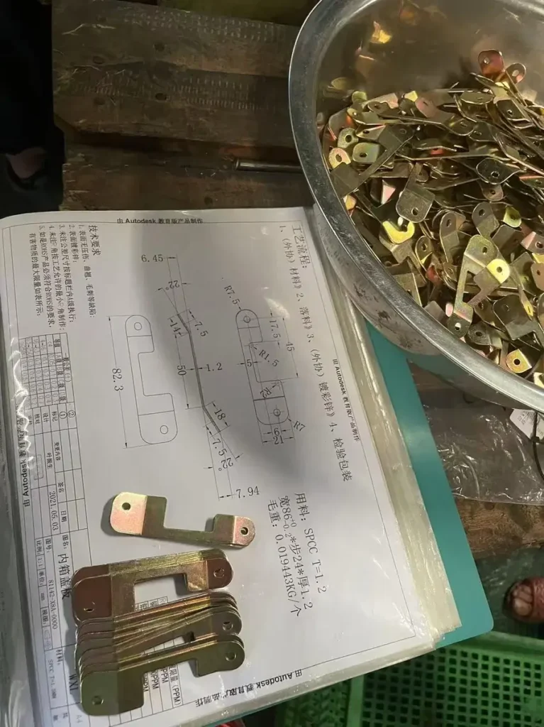
In one production scenario involving an iron motorcycle component, the part had already undergone stamping and was subsequently sent for electroplating. During the plating process, multiple components were handled together at one time, resulting in deformation on some parts.
To address the deformed components, the factory used a single-operation rework die designed specifically to restore the correct shape. Beyond specialized post-processing tasks, the factory also uses single-operation dies for specific production requirements when order quantities are not high. This observation shows how standalone tooling can be used for targeted rework or certain lower-quantity production requirements.
Case Study B – Progressive Tooling for Phosphor Bronze Electrical Components
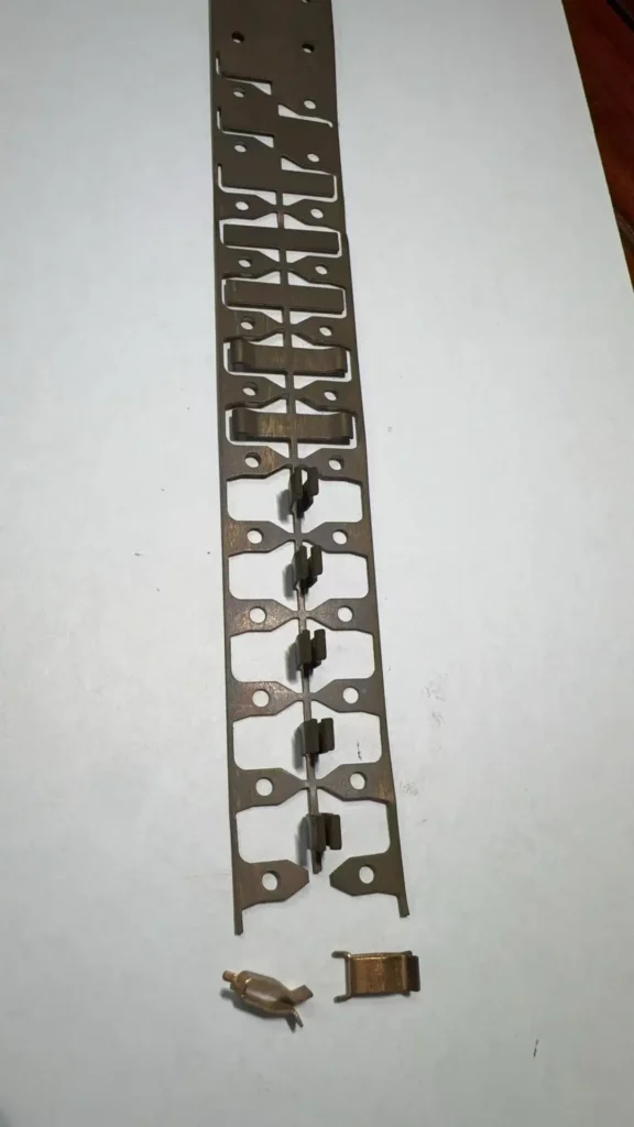
Another manufacturing example involves an internal electrical component used inside power strips and wall sockets. The part is produced from continuous phosphor bronze strip stock to meet an elasticity and spring-function requirement.
To produce the component, a progressive die was implemented. The phosphor bronze strip feeds continuously through the tooling, advancing through sequential operations until the completed component is produced. This application demonstrates how material selection, continuous stock
handling, and required manufacturing steps are evaluated together in a production setting.
Validating Tooling Strategy Through DFM Feasibility Review
Once a preliminary tooling direction is identified, it should be validated through a Design for Manufacturability (DFM) feasibility review. DFM validation helps evaluate whether the preliminary tooling
concept is practical for the manufacturing requirements before the tooling strategy is finalized.
Key areas reviewed during a DFM evaluation include:
- Part Geometry Feasibility: Reviewing feature layouts, spacing, and formed elements relative to standard tooling practices.
- Required Operation Sequencing: Evaluating the order of cutting, forming, and bending steps to maintain part stability.
- Material and Thickness Behavior: Assessing material characteristics, temper, and thickness responses under forming conditions.
- Critical Tolerance / Feature Relationships: Reviewing dimensional callouts and relative feature locations to support repeatable processing.
- Strip or Part Handling: Assessing how material feeds or moves through the tooling layout.
- Equipment Compatibility: Verifying tool fit relative to press capabilities and operational constraints.
- Secondary Operation Integration: Reviewing any post-stamping steps or in-die additions where applicable.
DFM serves as a validation layer to identify potential manufacturing concerns early and refine the tooling concept prior to tool construction.
RFQ Preparation Checklist for Stamping Tooling Quotes
Preparing a complete technical package enables toolmakers to evaluate project feasibility and provide an accurate tooling assessment.
Stamping Tooling RFQ Information Checklist
| Required Information | What OEM Should Provide | Why It Matters |
|---|---|---|
| Part Drawing and/or 3D Model | 2D engineering drawing and 3D CAD files showing part geometry and specifications | Defines part features, tooling feasibility, and required manufacturing operations |
| Material Specification | Alloy grade, material standard, temper, or hardness condition where applicable | Determines forming behavior, tooling requirements, and process feasibility |
| Material Thickness | Nominal thickness and applicable thickness tolerances | Affects die design, forming conditions, and dimensional control |
| Critical Dimensions / Tolerances | Functional dimensions, hole locations, feature relationships, and tight tolerance requirements | Defines quality expectations and required process control methods |
| Functional Requirements | End-use requirements, assembly conditions, and performance expectations | Helps determine manufacturing approach and critical features |
| Estimated Production Volume | Annual demand, initial order quantity, and expected batch sizes | Supports tooling investment evaluation and production strategy selection |
| Secondary Operations | Required post-stamping processes such as machining, deburring, welding, or assembly | Determines the complete manufacturing process flow |
| Surface Finishing | Plating, coating, painting, anodizing, or other finishing requirements | Affects downstream processing, dimensions, and final part performance |
| Special Quality or Application Requirements | Inspection criteria, industry standards, certifications, or special handling requirements | Ensures the tooling and production plan meets application-specific expectations |
Frequently Asked Questions (FAQ)
What main factors determine stamping die selection?
Stamping die selection depends on evaluating part geometry, material properties and thickness, dimensional tolerances, production requirements, estimated volume, tooling investment, equipment compatibility, and supporting manufacturing considerations.
How does production volume affect stamping die selection?
Production volume is one input in the overall evaluation. It should be considered together with part complexity, production requirements, tooling investment, and manufacturing strategy. No universal volume threshold determines die type.
How does part geometry influence tooling selection?
Part geometry helps determine the necessary cutting, bending, or forming steps. Complex shapes or features located in close proximity require carefully evaluated operation sequences across one or more die setups.
Why do material type and thickness matter in die selection?
Material properties and thickness affect forming behavior and tooling feasibility, so they must be evaluated together with part geometry and required operations.
How do tolerance requirements impact tooling strategy?
Tight tolerances and critical feature relationships affect how part positioning and process controls are evaluated. Tooling strategies must accommodate consistent feature location and indexing to maintain required tolerances across production.
What technical information is needed for a stamping tooling quote?
An RFQ package typically includes a part drawing and/or 3D model, material specification, stock thickness, critical dimensions and tolerances, functional requirements, estimated production volume, secondary operations, surface finishing requirements, and any special quality or application requirements.
Why is DFM validation necessary before building a stamping die?
DFM validation reviews part geometry, material behavior, and operation sequencing to help determine whether the preliminary tooling direction is practical before the tooling strategy is finalized.
Conclusion and Sourcing Next Steps
Selecting the right metal stamping die requires evaluating part geometry, material characteristics, tolerance expectations, production requirements, and tooling investment together. By applying a structured framework and validating concepts through DFM, engineering and procurement teams can identify a practical tooling strategy aligned with project goals.
If you are evaluating a custom metal stamping project, submit your part drawings, material specifications, stock thickness, and estimated production volumes to our engineering team for a manufacturing and tooling feasibility review.