Understanding how to choose the right metal stamping process for a custom component starts with balancing several core engineering and procurement variables: part geometry, target production volume, material grade and thickness, required dimensional tolerances, available tooling capital, and necessary secondary operations. There is no single universal metal stamping process; the suitable choice depends on how these factors interact for a specific part design.
For mechanical engineers, B2B procurement managers, and OEM sourcing teams, evaluating the stamping method early in the product development cycle is helpful. Aligning part features with an appropriate press and die configuration can help manage initial capital expenditure, control per-part unit costs, and minimize redesigns during production scaling.
How to Choose the Right Metal Stamping Process: Key Factors
Evaluating a custom sheet metal component for production requires examining six key variables. These factors dictate whether a part can be produced in a single press stroke, requires a continuous strip feed, or benefits from individual part handling between forming stations.
Part Geometry and Forming Complexity
The physical structure of the part is a primary technical constraint. Flat components with basic outer contours and simple punched holes typically require fewer forming steps. As the design incorporates additional features—such as multiple bends, drawn features, extruded holes, or tight internal radii—the component requires sequential forming steps. Deep cylindrical, box-shaped, or recessed geometries require controlled material flow during forming, which steers process selection toward drawing or multi-stage forming methods.
Production Volume
Target volume requirements heavily influence the economics of tooling amortisation. Lower-volume runs or short production cycles may not justify the upfront investment of a fully automated, multi-station die. Higher-volume components with extended product lifecycles allow initial tooling costs to be amortised over a larger number of total units, making automated, continuous stamping routes more cost-effective per piece over time.
For a broader production-strategy evaluation covering batch size, demand stability, design maturity, tooling exposure, and program lifespan, see our low-volume vs high-volume metal stamping guide.
Material Type and Thickness
Sheet metals respond differently to plastic deformation based on their yield strength, tensile strength, and elongation characteristics. Ductile materials like low-carbon steel, soft aluminum alloys, and brass generally form without cracking. High-strength alloys, spring-tempered materials, and stainless steels can exhibit notable springback and may require higher press forces. Thicker stock generally requires greater forming force and appropriately designed tooling, while thin-gauge materials demand precise tool clearances.
For a deeper framework covering strength, formability, corrosion resistance, conductivity, temper, and material cost, see our metal stamping material selection guide.
Tolerance and Repeatability
Critical dimensions—such as hole center distances, specific bend angles, and flat seating surfaces—influence die construction and station layout. High-precision features that must remain consistent across production runs often benefit from integrated tooling operations that reduce manual repositioning errors between separate machines.
Tooling Investment and Part Cost
Every metal stamping project involves a trade-off between upfront tooling expense (Non-Recurring Engineering, or NRE) and the recurring unit price (Piece Price). Complex, multi-station tooling carries higher initial development costs but can yield lower unit labor costs. Simpler, modular tooling minimizes initial capital risk but may increase unit handling and processing costs over time.
Secondary Operations
Downstream assembly requirements directly impact the initial tooling strategy. If a part requires threaded holes, inserted hardware (such as clinch nuts or studs), localized welding, edge deburring, or protective surface coatings, engineers can evaluate whether to integrate these features directly into the press tooling or perform them as separate offline processes.
| Project Requirement | Recommended Process Direction | Main Reason |
|---|---|---|
| Simple flat parts, lower volume | Single-stage stamping | Lower tooling investment and flexible production |
| Small-to-medium parts, repeat production | Progressive die stamping | Multiple operations integrated in one die |
| Large or complex formed parts | Transfer die stamping | Allows individual part handling between stations |
| Deep hollow shapes | Deep draw stamping | Controlled material flow into formed cavities |
| Flat precision parts requiring simultaneous cutting | Compound die stamping | Multiple cutting operations in one press stroke |
Main Metal Stamping Processes and When to Choose Them
Understanding when to consider specific die configurations helps ensure that your component’s structural needs match an appropriate forming technology.
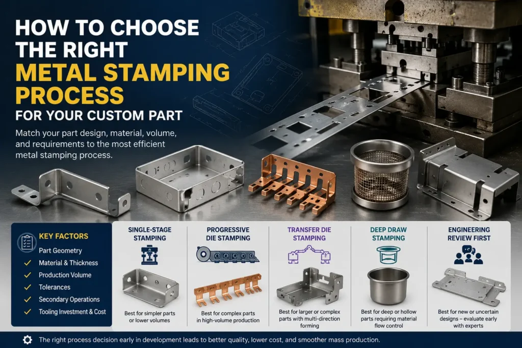
Single-Stage Stamping — Best for Simpler or Lower-Volume Parts
Single-stage dies (also referred to as stage dies or simple station dies) perform one primary action—such as blanking, punching, or bending—with each press stroke. An operator or a manual feed mechanism moves the part between workstations or individual presses to complete the required steps.
- When to Choose: Often considered for lower production volumes, large structural components that exceed standard press bed sizes, or early-stage product revisions where tooling flexibility is preferred.
- Limitations: Typically higher labor costs per unit, slower production speeds, and increased handling between operations.
Progressive Die Stamping — Best for Repeat High-Volume Production
Progressive die stamping utilizes a continuous strip of coiled metal that feeds sequentially through a series of inline workstations within a single die set. Each stroke of the press advances the strip, performing operations such as piercing, notch blanking, coining, or bending at distinct stations. The part is severed from the carrier strip at the final station.
- When to Choose: Well-suited for medium-to-high volume production of small-to-medium components requiring repeatable dimensions and minimal manual handling.
- Limitations: Requires higher initial tooling investment, rigid setup procedures, and consistent material coil width and pitch tolerances.
Transfer Die Stamping — Best for Larger or Complex Multi-Stage Parts
Unlike progressive die stamping, where the part remains attached to a continuous metal carrier strip, transfer die stamping detaches the raw blank from the strip at an early station. Mechanical transfer fingers or automated arms then pick up the individual part and advance it through consecutive forming stations within the press.
- When to Choose: Often selected when a part features larger dimensions, deep cutouts, or complex contours that make keeping the part tethered to a continuous strip impractical, or when a part requires rotational positioning between forming passes.
- Limitations: Requires specialized press setups with transfer automation, leading to higher initial setup expenses and moderate press cycle speeds.
Deep Draw Stamping — Best for Deep or Hollow Geometries
Deep draw stamping (or drawing) is evaluated when flat sheet material must be formed into hollow, recessed, cylindrical, or box-shaped geometries through controlled plastic material flow into a die cavity under blank-holder pressure. Process feasibility depends on the part geometry, draw ratio, material ductility, thickness, and required forming stages.
- When to Choose: Typically evaluated for seamless cylindrical containers, enclosures, hollow housings, and round cup geometries where a seamless structure is desired.
- Limitations: Requires suitable material ductility, appropriate lubrication, and careful multi-stage tool design to manage wall thinning or material splitting.
Compound / Secondary Stamping Routes — When Multiple Operations Are Better Than One Complex Die
Compound dies perform multiple cutting operations (such as simultaneous inner punching and outer blanking) in a single press stroke at one station. In other scenarios, combining a simple primary stamping step with secondary CNC bending, press brake forming, or offline hardware insertion provides a practical alternative to constructing a single, highly intricate multi-station tool.
- When to Choose: Useful for flat, high-precision washers, thin discs, or low-to-medium volume parts where building a multi-station progressive die may not be economically justified.
- Limitations: Primarily restricted to flat or shallow forming profiles per station.
Metal Stamping Process Selection Matrix
The following decision matrix provides a preliminary guide for aligning key project parameters with a practical stamping process direction:
| Project Condition | Likely Process Direction | Key Engineering & Economic Rationale |
|---|---|---|
| Simple geometry + lower volume | Single-Stage Stamping | Helps minimize upfront tooling investment; practical for lower initial capital. |
| Multiple features + repeat high volume | Progressive Die Stamping | Higher production throughput; integrated inline operations help reduce unit labor costs. |
| Large / complex multi-stage part | Transfer Die Stamping | Allows part separation from the strip; provides flexibility for multi-angle forming. |
| Deep / hollow 3D geometry | Deep Draw Stamping | Facilitates controlled material flow to form hollow cavities. |
| Flat, high-precision profile + tight flat tolerance | Compound Die Stamping | Promotes concentricity and flat hole profiles within a single stroke. |
| Uncertain / evolving part design | Engineering Review First | Helps avoid premature capital expenditure on rigid mass-production tooling. |
This matrix is a preliminary selection guide rather than a fixed manufacturing rule. Final process selection should be based on part drawings, material condition, tolerances, production volume, and a formal DFM review.
A Step-by-Step Decision Framework for Choosing a Stamping Process
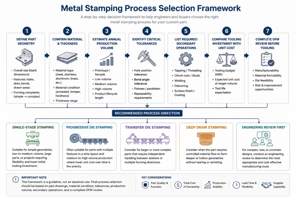
To evaluate a custom sheet metal component systematically, consider following this seven-step decision sequence before committing to tooling development:
Step 1 — Define the Part Geometry
Identify the core shape requirements. Is the part flat, bent across one or two axes, or characterized by drawn features? Measure the overall dimensions, maximum depth, and hole density.
Step 2 — Confirm Material Grade and Thickness
Specify the exact alloy grade, temper, and sheet thickness. Assess whether the material possesses sufficient ductility for the required forming steps without cracking or excessive springback.
Step 3 — Estimate Annual Production Volume
Determine the initial batch size, estimated annual volume, and anticipated product lifespan. This helps define an appropriate Non-Recurring Engineering (NRE) tooling budget.
Step 4 — Identify Critical Tolerances
Highlight tight hole-center distances, critical flat seating planes, and bend angle tolerances on 2D engineering drawings. Distinguish between critical functional tolerances and standard commercial limits.
Step 5 — List Required Secondary Operations
Determine if downstream features—such as threaded clinch nuts, spot-welded brackets, tapped holes, or surface plating—are required. Evaluate whether these can be integrated inline or handled offline.
Step 6 — Compare Tooling Investment With Unit Cost
Calculate total project expenditure across the expected production volume. Compare the payback timeline of a higher-cost progressive tool against the higher unit price of a simpler single-stage setup.
Step 7 — Complete DFM Review Before Tooling
Submit 2D drawings and 3D CAD models to your stamping manufacturer for a Design for Manufacturability (DFM) review. Verify bend radii, die clearances, and material utilization prior to tooling fabrication.
| Selection Step | Key Question |
|---|---|
| Part Geometry | Is the part flat, bent, drawn, or multi-featured? |
| Material | Is the alloy suitable for the required forming operation? |
| Volume | Does production demand justify dedicated tooling? |
| Tolerance | Which dimensions require process control? |
| Secondary Operations | Should additional processes be integrated or performed offline? |
| Cost | Does tooling investment match expected production volume? |
| DFM Review | Can the design be manufactured reliably before tooling starts? |
How Production Volume Changes the Best Stamping Strategy
Production scale directly impacts the economics of process selection. A component that begins its lifecycle as a low-volume part may benefit from a different manufacturing strategy if market demand scales over time.
During early prototyping or initial pilot runs, building complex automated tooling carries higher financial risk. Simple laser-cut blanks combined with stage-die bending or press brake forming allow engineering teams to validate fit and function without committing significant capital to multi-station tools.
As demand shifts toward stable medium or high annual volumes, the economic priority often moves from minimizing tooling expense to controlling unit costs and cycle times. At this stage, transitioning the part design to an automated progressive die or transfer die setup can cut manual handling steps and support dimensional repeatability across larger manufacturing lots.
Tooling Cost vs. Unit Cost: Avoid Choosing by Piece Price Alone
Evaluating process options solely on the per-piece price quote without considering initial tooling capital and long-term production volume can lead to sub-optimal procurement decisions.
Selecting a process based only on the lowest initial tooling quote may result in higher unit labor costs, additional deburring steps, or manual handling. Conversely, investing heavily in a high-speed progressive die for a part with uncertain annual demand can tie up capital in tooling that may not reach its financial break-even point.
Procurement decision-makers often evaluate total project cost using a balanced framework:
Total Project Cost=Tooling NRE Investment+(Annual Production Volume×Unit Piece Cost)+Secondary Processing Expense
This is a simplified procurement framework; actual project cost may also include material utilization, tooling maintenance, inspection, packaging, logistics, and other project-specific costs.
| Cost Factor | Impact on Process Selection |
|---|---|
| Tooling NRE | Determines initial capital requirement |
| Unit Piece Cost | Influences long-term production economics |
| Material Utilization | Affects raw material efficiency |
| Secondary Operations | Adds processing and handling costs |
| Maintenance | Impacts long-term tooling stability |
| Inspection Requirements | Affects quality control cost |
Real Manufacturing Examples: Matching Parts to Stamping Processes
Examining how material properties and functional geometry dictate process selection highlights the practical application of engineering principles.
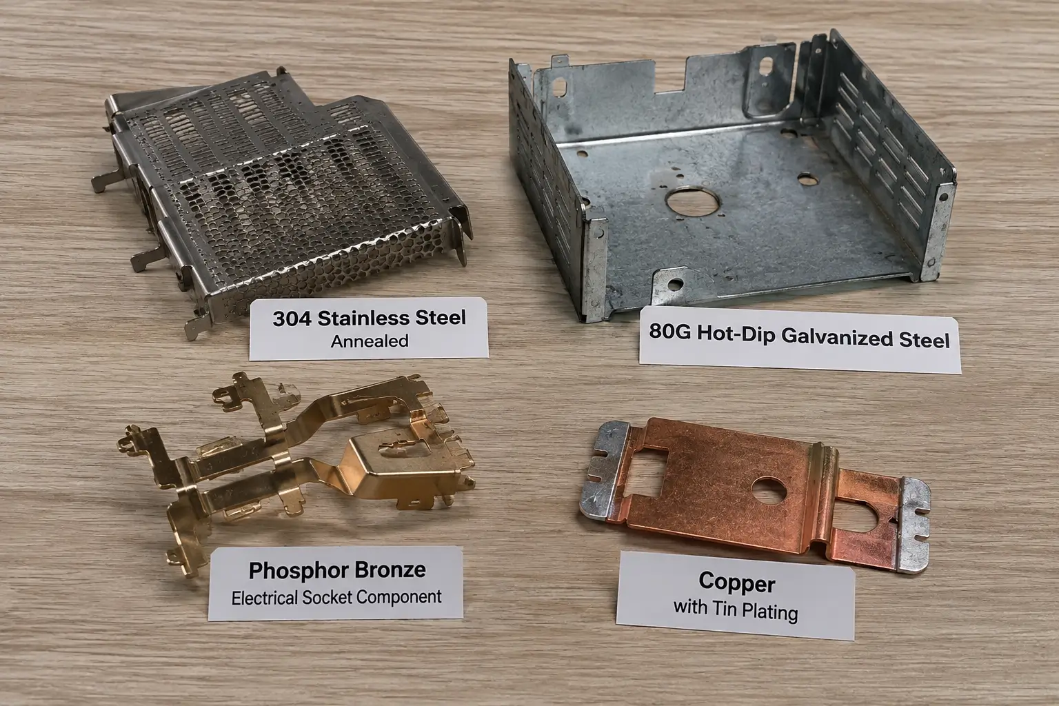
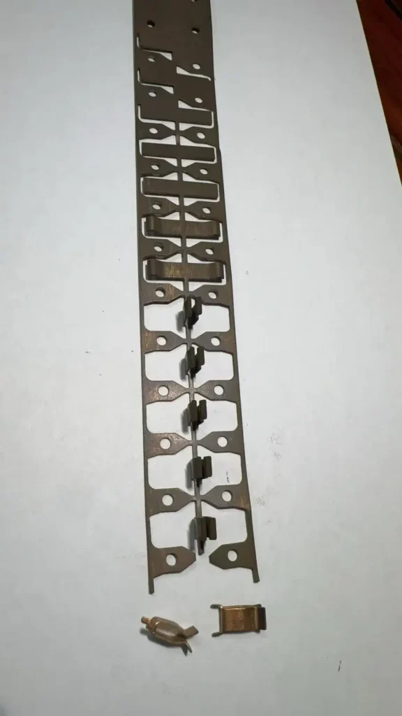
Phosphor Bronze Electrical Component — Progressive Die
In this electrical socket component application, phosphor bronze was used as an elastic conductive material. To produce these small spring-action terminal parts from continuous coil stock, a progressive die route is typically utilized. The material feeds sequentially through inline stations from raw strip to finished part, accommodating the elastic nature of the alloy while completing forming operations in a continuous press setup.
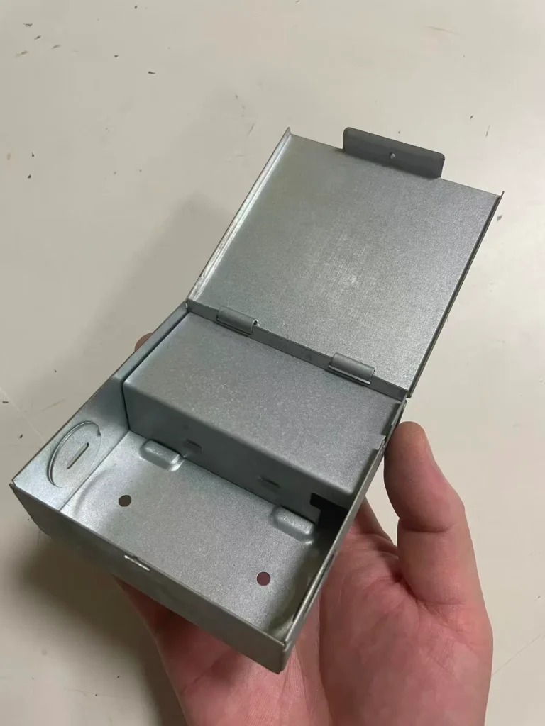
Galvanized Steel Power Box — Multi-Stage Progressive Production
Power box enclosures manufactured from 80G hot-dip galvanized steel sheet require multiple forming steps to achieve their final housing geometry. A multi-stage progressive die setup allows the sheet material to undergo sequential punching, blanking, and forming operations directly from the raw material coil through to the finished box, providing a practical production path for parts involving a series of sequential bends and features.
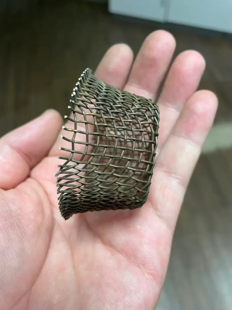
Annealed 304 Stainless Steel Component — Drawing/Formability Decision
Austenitic 304 stainless steel offers good corrosion resistance and strength, but can work-harden during aggressive forming operations. In a specific manufacturing application involving a 304 stainless steel mesh component requiring drawing operations, the material required an annealed state prior to forming. In this case, un-annealed material was not suitable for the required drawing process, and the annealing treatment altered the surface color to black. This real-world example demonstrates that material condition and heat treatment state can directly determine whether a specific forming process is feasible for a given part.
Common Mistakes When Selecting a Metal Stamping Process
- Choosing by Tooling Price Alone: Selecting a setup solely based on the lowest initial die charge without evaluating whether the resulting simple tooling requires higher manual labor or secondary handling on every unit produced.
- Assuming High Volume Automatically Mandates Progressive Dies: Overlooking physical part size, drawn depth, or carrier strip constraints. Large or exceptionally wide components may require transfer dies or compound setups regardless of total quantity.
- Ignoring Material Formability and Grain Direction: Designing tight bend radii without evaluating alloy ductility or rolling grain direction, which can lead to micro-cracking along outer bend lines.
- Specifying Unnecessarily Tight Tolerances: Applying unnecessarily strict tolerances to non-critical external features, which may require complex multi-station restrike tooling instead of standard commercial die structures.
- Forgetting Secondary Operations During Tooling Planning: Failing to account for downstream clinch nut insertion, tapping, or surface finishing during initial die design, which can result in unplanned offline handling costs.
What Information Should You Send a Stamping Manufacturer for Process Evaluation?
To enable a metal stamping manufacturer to evaluate part feasibility and recommend an appropriate production process, OEM buyers should provide a complete RFQ package including drawings, material specifications, production requirements, and critical quality expectations. The following checklist summarizes the key information required for accurate process evaluation.
Metal Stamping Process Evaluation RFQ Checklist
| Required Information | Why It Matters |
|---|---|
| 2D Engineering Drawings | Defines dimensions, tolerances, and critical features |
| 3D CAD Models | Allows evaluation of formed geometry |
| Material Specification | Determines forming feasibility |
| Annual Volume | Supports tooling and process selection |
| Critical Tolerances | Identifies precision requirements |
| Secondary Operations | Defines complete manufacturing route |
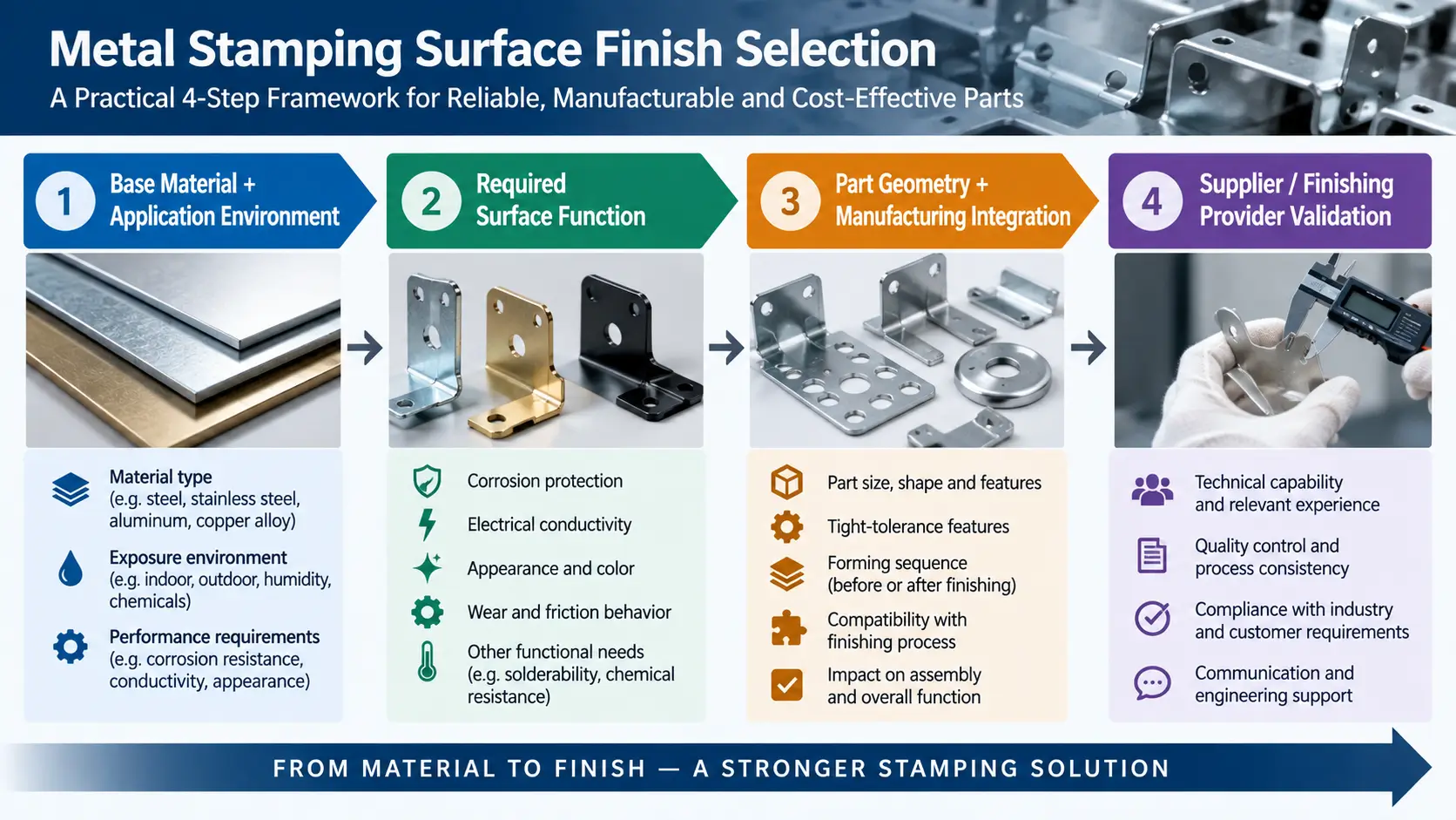
| Surface Finish Requirements | Determines downstream processing needs |
Have a Custom Stamped Part to Manufacture?
Share your 2D/3D drawings, material requirements, annual volume, tolerances, and secondary operations with Metal Stamp Factory for process evaluation and quotation.
Frequently Asked Questions About Choosing a Metal Stamping Process
How do I determine which metal stamping process to use?
Evaluate the part’s geometry, annual production volume, material grade, sheet thickness, and critical tolerances. Simple, lower-volume components often lean toward single-stage dies, while multi-feature, higher-volume parts are frequently suited for progressive or multi-stage tooling setups.
Is progressive die stamping always best for high-volume parts?
Not always. While progressive dies offer efficient production for small-to-medium parts, very large components or deep drawn geometries may require transfer die stamping or dedicated drawing operations due to carrier strip and press bed limitations.
When should I choose transfer die stamping?
Consider transfer die stamping when a component is too large or complex to remain attached to a continuous material strip, requires 3D rotational positioning between forming steps, or features multi-station deep drawn profiles.
When is deep draw stamping required?
Deep draw stamping is evaluated when flat sheet material must be formed into hollow, recessed, cup-shaped, or box-like geometries that require controlled plastic metal flow into a die cavity. Feasibility depends on geometry, draw ratio, material ductility, and thickness.
Can metal stamping be economical for low-volume production?
Yes. Low-volume metal stamping can be practical when using modular single-stage dies, universal unit tooling, or compound dies that help limit initial NRE tooling capital while producing clean punched features.
How does material thickness affect stamping process selection?
Thicker materials generally require greater forming force and may require more robust tooling and larger minimum bend radii, depending on the material and part geometry.
What information does a manufacturer need to recommend a stamping process?
A manufacturer typically needs 2D drawings with tolerances, 3D STEP models, material alloy and thickness specifications, target annual quantities, surface finishing requirements, and secondary assembly details.