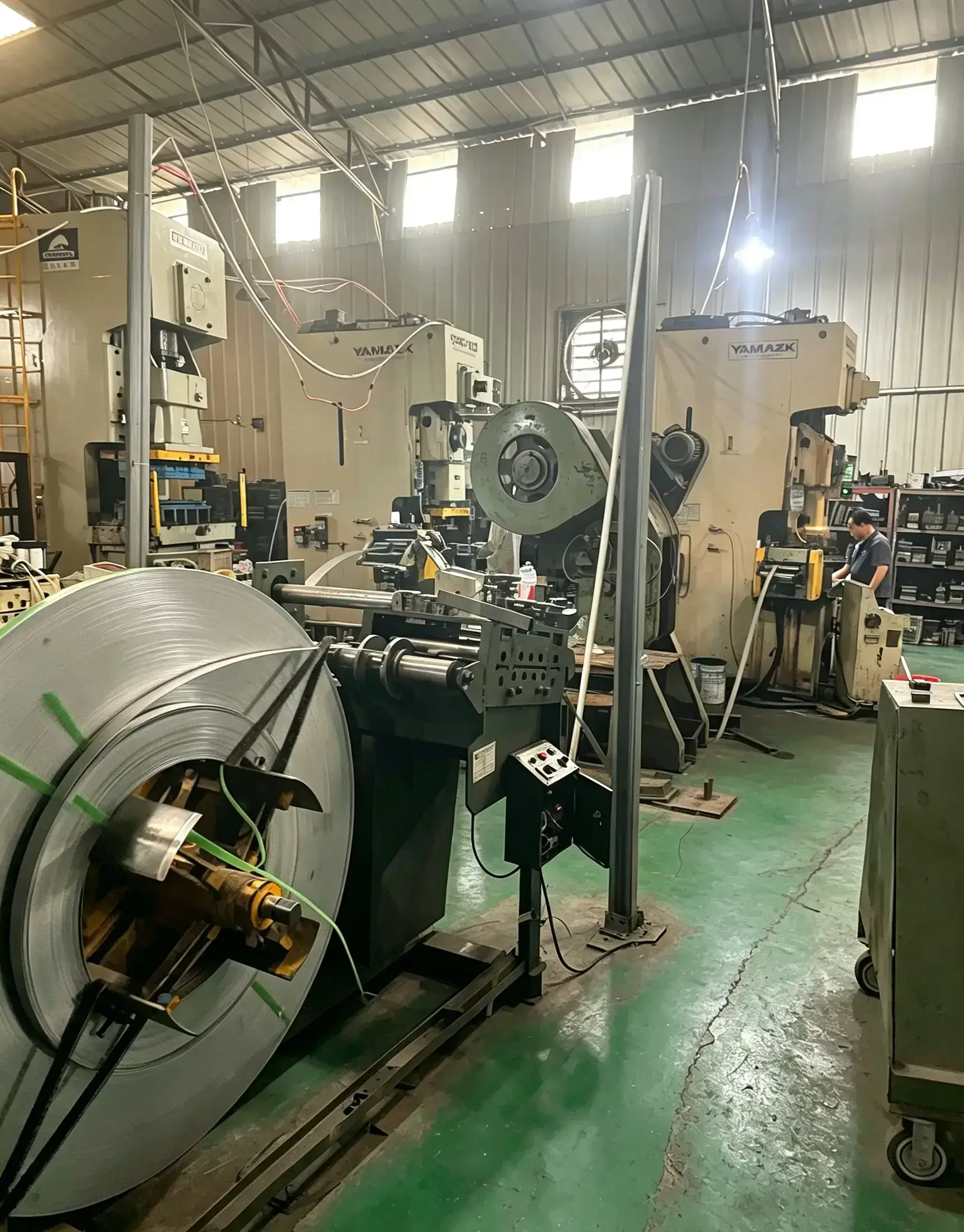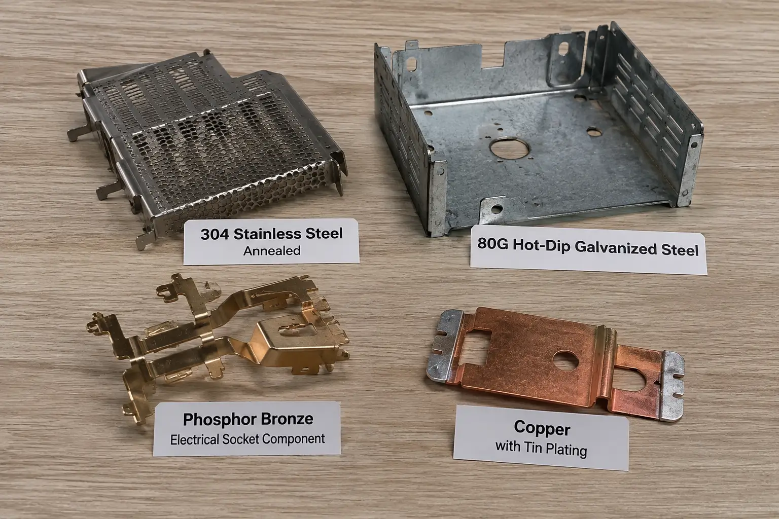
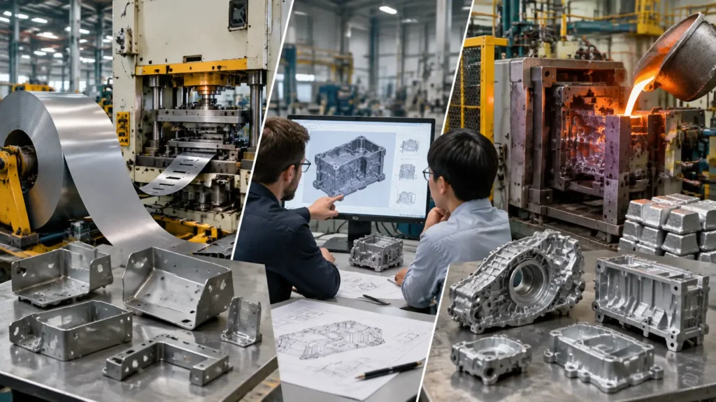
When evaluating manufacturing processes for custom metal components, OEM engineers and procurement teams frequently compare metal stamping vs die casting. Both can support automated repeat production and complex metal components with strong process repeatability, but they rely on fundamentally different material inputs, thermal conditions, and forming mechanisms.
Evaluating metal stamping vs die casting requires looking beyond simple per-part quotes. A complete engineering comparison must consider raw material compatibility, baseline geometry, tooling investment, secondary processing steps, lifetime program volumes, and mechanical performance requirements. Choosing between stamping and die casting is rarely a matter of finding a universally superior process; rather, it is about aligning part design requirements with the inherent capabilities and economic profiles of each manufacturing route.
Metal Stamping vs Die Casting: Quick Comparison
The following overview summarizes the core technical and operational differences between metal stamping and die casting.
Starting Material Metal Stamping: Cold-rolled or hot-rolled sheet metal, strip, coil, or discrete flat blanks. Die Casting: Ingot or liquid metal stock melted into a molten state prior to injection.
Material Compatibility Metal Stamping: Broad range of ferrous and non-ferrous sheet metals, including carbon steel, stainless steel, aluminum, copper alloys, and brass. Die Casting: Commercially centered on non-ferrous alloys, primarily aluminum, zinc, and magnesium.
Part Geometry Metal Stamping: Constant-thickness sheet-formed structures featuring bends, draws, flanges, embossments, and pierced features. Die Casting: Three-dimensional cast geometries with variable wall sections, internal bosses, integrated structural ribs, and complex contours.
Tooling / NRE Metal Stamping: Dedicated hardened steel progressive, stage, or transfer dies designed to cut and form sheet metal. Die Casting: Reusable hardened steel cavities (dies) designed to withstand high pressure and thermal cycling.
Unit Economics Metal Stamping: High speed press cycles with material utilization driven by strip layout and scrap management. Die Casting: Cycle times governed by alloy solidification and thermal management, with material utilization linked to gating and runner trimming.
Secondary Operations Metal Stamping: Deburring, secondary forming, hardware installation, welding, machining, and surface finishing as required. Die Casting: Gate/runner trimming, flash removal, precision machining/tapping of tight features, and surface finishing as required.
Part Consolidation Metal Stamping: Achieved by joining multiple stamped components via spot welding, mechanical fasteners, or continuous assembly. Die Casting: Achieved by integrating multiple structural features, bosses, and brackets into a single cast component.
Typical Process Risks Metal Stamping: Material springback, burr formation, edge splitting, wrinkling during draw operations, and tool wear. Die Casting: Gas porosity, shrinkage voids, cold shuts, misruns, thermal fatigue (die crazing), and component warpage.
Design Changes Metal Stamping: Requires modification of punch/die inserts, wire EDM rework, or replacement of dedicated station tooling. Die Casting: Requires CNC re-machining of die cavities, core pin modifications, or structural welding and re-sinking of tool steel.
Best-Fit Decision Logic Metal Stamping: Often well suited to sheet-based structural components, brackets, housings, and applications where steel, stainless steel, aluminum, or other suitable sheet materials meet the engineering requirements. Die Casting: Often well suited to complex 3D non-ferrous components where integrated ribs, bosses, pockets, mounting features, or part consolidation provide functional or manufacturing value.
Core Process & Material Differences
Understanding the fundamental physical mechanisms of metal stamping and die casting is essential for evaluating which process best fits a specific component drawing.
How Metal Stamping Works
Metal stamping mechanically cuts and/or forms sheet, strip, coil, or blanks using dedicated tooling mounted in a press. Depending on the part design, the tooling may perform shearing operations such as blanking and piercing, forming operations such as bending and drawing, or multiple cutting and forming operations within the same production sequence.
The stamping process encompasses a wide range of press operations, including:
- Blanking and Piercing: Shearing external contours or internal holes out of the metal strip.
- Bending and Flanging: Folding the metal along linear axes to create angled walls, stiffness ribs, or mating edges.
- Deep Drawing: Stretching a flat sheet blank over a punch into a hollow, three-dimensional cup, shell, or box geometry.
- Coining and Embossing: Displacing metal under extreme pressure to imprint fine surface details, raise localized features, or alter section thickness.
For repeat production, metal stamping may use progressive dies, transfer systems, or other dedicated die configurations depending on part geometry, production requirements, and tooling strategy. In progressive stamping, a continuous strip of sheet metal feeds through sequential stations, where each stroke of the press performs a specific cutting or forming action until the completed part is detached at the final station.

How Die Casting Works
Conventional high-pressure die casting (HPDC) is a liquid metal forming process in which molten metal alloy is injected under high velocity and pressure into a reusable steel mold, known as a die.
The die casting process generally follows these steps:
- Melting: Non-ferrous metal ingots are melted in a furnace to maintain a specific pouring temperature.
- Injection: Molten metal is metered into a shot sleeve and driven by a hydraulic piston into the closed die cavity at high speeds.
- Solidification: The molten alloy cools and solidifies within the die cavity while process pressure and thermal conditions are controlled to support the required casting geometry and quality.
- Ejection: The die splits along its parting line, and ejector pins push the solidified casting out of the tool.
- Post-Casting Processing: The raw casting exits with attached gates, runners, overflow wells, and flash, which are trimmed off mechanically prior to secondary operations.
Die casting relies heavily on fluid dynamics and thermal control within the mold to ensure full cavity fill before the alloy solidifies.
Material Compatibility: Ferrous and Non-Ferrous Alloys
Material selection represents one of the sharpest distinctions when comparing die casting vs metal stamping.
Conventional high-pressure die casting is commercially centered on non-ferrous alloys, specifically aluminum, zinc, and magnesium. These materials possess relatively low melting points, favorable fluid flow characteristics, and cooling properties that preserve the service life of steel tooling. Conventional high-pressure die casting is generally not a practical commercial route for steel or stainless steel. Steel and stainless steel generally present severe thermal shock and tooling challenges in HPDC due to their elevated processing temperatures.
Metal stamping, by contrast, can process a broad spectrum of sheet alloys. Depending on material grade, temper, thickness, geometry, tooling, and forming requirements, commonly stamped materials include:
- Low-carbon and high-strength low-alloy (HSLA) steels
- Stainless steels (300 and 400 series)
- Aluminum alloys (wrought series such as 5000 and 6000 series)
- Copper, brass, and bronze alloys
However, material choice in stamping is bounded by ductility and strain hardening. An alloy that lacks sufficient elongation may crack or split during severe bending or deep drawing. OEM engineers must match the material grade and temper to the intended forming severity.
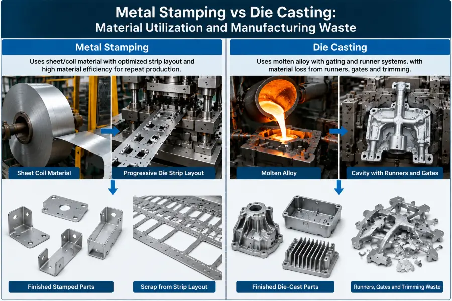
Material Utilization and Manufacturing Waste
| Factor | Metal Stamping | Die Casting |
|---|---|---|
| Material Form | Sheet, strip, coil, or blanks | Molten alloy ingots |
| Material Efficiency | Optimized through nesting and strip layout | Influenced by cavity filling, runners, gates, and trimming waste |
| Waste Source | Scrap skeleton, blanking waste, and nesting loss | Runners, gates, flash, and trimming waste |
| Optimization Method | Progressive die layout and material utilization studies | Casting simulation, gating design, and process optimization |
Part Geometry: Sheet-Formed Features vs. 3D Cast Structures
The geometry of a metal part is dictated directly by whether the process starts with a solid sheet of uniform gauge or a liquid alloy.
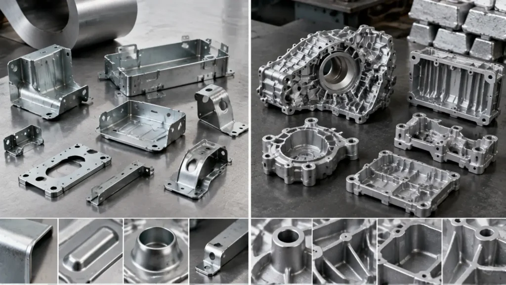
Stamped Geometry: Sheet Gauge, Bends, Draws and Formed Features
Because metal stamping begins with raw sheet or coil stock, the initial gauge of the material largely defines the base wall thickness across the finished component. While operations like coining can cause minor localized displacement of metal, stamping does not naturally vary wall thickness dramatically within a single piece.
Stamping achieves structural rigidity not through thick sections, but through geometric stiffening features. Designers add strength to light-gauge sheet metal by incorporating:
- Formed radii, hemmed edges, and perimeter flanges
- Stiffening beads, ribs, and embossed gussets
- Drawn box shapes, cups, or stepped transitions
Stamping is well suited to many flat, bent, drawn, and otherwise formed sheet-metal components such as brackets, structural members, shields, contact plates, housings, and enclosures.
Die-Cast Geometry: Walls, Ribs, Bosses and Pockets
Die casting operates without the constant-thickness constraint of sheet metal. Because liquid alloy fills a custom-machined cavity, die casting can create complex three-dimensional forms with features oriented across multiple planes.
Common die-cast geometric capabilities include:
- Integrated mounting bosses with deep internal blind holes
- Heavy structural ribs transitioning into thinner outer walls
- Complex external heat-sink fins, fluid channels, and mounting flanges
- Varied section thickness across a single integrated component
However, die-cast geometric freedom is subject to casting-specific Design for Manufacturability (DFM) rules. Abrupt section changes can contribute to uneven solidification, thermal stress, and increased risk of shrinkage-related defects. Therefore, sound die-cast design generally uses appropriate wall transitions, internal radii, fillets, and application-appropriate draft to support filling, solidification, and reliable ejection.
Multi-Piece Stamped Assembly vs. Consolidated Die Casting
A critical point of evaluation for sourcing managers and design engineers is whether a multi-part sheet metal assembly should be converted into a single, consolidated die-cast component.
When Part Consolidation May Be Advantageous
When a product design relies on multiple stamped components joined together, assembly operations can add labor, fixtures, hardware, inspection, and tolerance-stack considerations. Converting a multi-piece stamped bracket or housing assembly into a single die-cast part may provide operational benefits under appropriate engineering conditions:
- Potential Reduction in Secondary Joining: A consolidated casting may reduce some spot welding, riveting, fastening, hardware installation, or other joining operations, depending on the redesigned component.
- Reduction in Assembly Tolerance Stack-Up: A single cast component can reduce tolerance stack-up associated with locating and joining multiple stamped components, although the casting itself remains subject to dimensional variation and process capability.
- Integrated Features: Bosses, alignment features, grooves, ribs, and other suitable geometry may be integrated into a casting, potentially reducing the need for separate brackets, hardware, or assembly operations.
- Simplified Supply Chain: Procurement handles a single part number rather than managing multiple stamped sub-components, hardware, and assembly fixtures.
When Retaining a Stamped Assembly Makes More Sense
Part consolidation via die casting is not automatically an advantageous engineering or economic choice. In many applications, retaining a multi-piece stamped assembly may remain the more appropriate engineering and economic choice:
- Material and Mechanical Requirements: If the application requires properties better matched by a particular sheet steel, stainless steel, aluminum, or other suitable sheet alloy, retaining a stamped design may be appropriate. Mechanical performance must be evaluated using the actual alloy, material condition, geometry, loading mode, manufacturing route, and application requirements rather than attributed to stamping or die casting alone.
- Tooling Risk and Capital Commitment: Engineering revisions after dedicated tooling is completed may require die modification, insert changes, re-machining, component replacement, and requalification. The cost and difficulty of those changes depend on the specific casting or stamping tool architecture and the extent of the design revision.
- Weight and Structural Efficiency: Stamped sheet structures and die-cast components achieve stiffness through different combinations of material properties and geometry. Weight should be compared using the actual alloy, wall or sheet thickness, ribs, flanges, load paths, joining strategy, and structural requirements rather than assuming either process automatically produces the lighter design.
- Existing High-Speed Infrastructure: If automated assembly lines for stamped parts are already established, the capital required to re-tool for die casting and post-machining may not deliver a favorable return on investment.
Tooling Investment, Unit Economics & Complete Route Costing
Evaluating the cost difference between stamping and die casting requires analyzing Non-Recurring Engineering (NRE) tooling expense alongside total piece-part manufacturing routes.
Stamping Dies vs. Die-Casting Tooling
Both metal stamping and die casting require substantial upfront investments in dedicated tooling, but the nature of that tooling differs significantly.
Stamping tooling—such as progressive dies or stage tools—utilizes precision-ground tool steel punches, dies, stripper plates, and guide pins mounted within a die set. Cost factors are driven by the number of forming stations, part complexity, material type, and stroke speed requirements. Progressive dies intended for demanding repeat production may require carefully selected tool steels, wear-resistant inserts, coatings, or other tooling strategies depending on material, geometry, speed, and expected tool life.
Die-casting tooling consists of high-strength, heat-treated steel molds capable of enduring high injection pressures and extreme thermal cycling. Die-cast tools must incorporate internal cooling lines, runner systems, ejector pin mechanisms, and, where complex geometries are involved, hydraulic side-actions or moving cores. Thermal stress, erosion from liquid metal velocity, and mechanical fatigue dictate tool life and die maintenance schedules.
Neither tooling type is universally cheaper or more expensive. A relatively simple stamping die may require substantially less investment than a complex die-casting tool, while a highly complex multi-station progressive die may equal or exceed the investment required for a less complex casting tool.
| Cost Factor | Metal Stamping | Die Casting |
|---|---|---|
| Initial Tooling Investment | Depends on die complexity, number of stations, material requirements, and production speed | Depends on mold complexity, cavity count, cooling systems, slides, and thermal requirements |
| Material Cost | Based on sheet/coil material utilization and scrap management | Based on alloy cost, melting losses, runners, and trimming waste |
| Production Cost | Strong advantage when high-speed repeat production amortizes tooling cost | Strong advantage when complex geometry reduces assembly and secondary operations |
| Secondary Operations | May require welding, hardware installation, machining, or finishing | May require trimming, machining, tapping, and surface finishing |
| Long-Term Economics | Suitable for stable sheet-metal production programs | Suitable for integrated 3D components and part consolidation programs |
Why Universal Crossover Volumes Are Unreliable
A common misconception in manufacturing procurement is that there is a universal production volume threshold for choosing between processes.
Such universal crossover rules are unreliable for project-specific process selection. The exact economic crossover point between stamping and die casting depends entirely on part-specific variables:
- Material Costs: Raw sheet steel price per kilogram versus aluminum ingot price and burn-off losses.
- Press/Machine Cycle Times: High-speed mechanical stamping presses operating at high strokes per minute versus HPDC machines constrained by alloy solidification times.
- Tooling Longevity: The total amortized tooling cost per part over the lifetime of the program.
- Cavity / Station Count: Multi-cavity casting dies versus multi-progression stamping tools.
Comparing Complete Manufacturing Route Costs
Evaluating unit price based strictly on raw press or casting machine cycle time leads to inaccurate cost projections. Sourcing teams must analyze the complete manufacturing route from raw material input to final assembly integration.
Conceptual Stamping Route: Raw Sheet/Coil Stock -> Stamping Press Operations (Cut/Form) -> In-Die Tapping or Secondary Deburring -> Hardware Insertion / Spot Welding -> Surface Plating / E-Coating -> Final Quality Inspection.
Conceptual Die Casting Route: Alloy Melting -> HPDC Machine Injection -> Mechanical Gate/Runner Trimming -> Flash Removal / Shot Blasting -> CNC Machining (Mating Surfaces / Critical Holes) -> Drilling & Tapping -> Surface Powder Coating / Anodizing -> Final Quality Inspection.
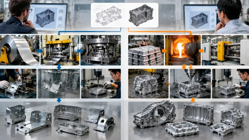
These routes are conceptual examples only. Individual components may omit many of these operations or require different secondary processes depending on geometry, material, surface requirements, tolerances, joining strategy, and final drawing specifications.
If a raw die casting requires extensive secondary CNC machining to meet critical drawing requirements, those downstream operations can materially change its total manufacturing cost. Conversely, if a stamped design requires extensive secondary welding, fastening, or assembly, a consolidated die casting may reduce some downstream operations and may improve total route economics when the material, geometry, quality requirements, and tooling strategy are suitable.
Quality, Defects and Dimensional Capability
Every manufacturing process introduces specific quality risks and dimensional traits that design engineers must anticipate during drawing release.
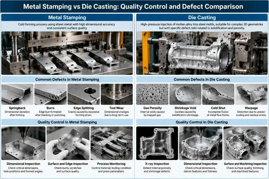
Stamping: Springback, Burrs, Splitting and Tool Wear
Quality control in metal stamping centers primarily on mechanical deformation behavior and tool wear:
- Material Springback: When forming pressure is released, sheet metal naturally attempts to elastically return to its original flat state. Tool designers must compensate for springback through over-bending or coining operations.
- Burr Formation: As cutting edges on punches and die buttons wear down, clearance increases, leading to raised material burrs along sheared edges that may require secondary deburring.
- Splitting and Wrinkling: Exceeding the forming limits of the sheet material causes localized thinning or tensile splitting in drawn walls, while excess material can wrinkle under compressive forces.
- Dimensional Shift from Tool Wear: Continuous high-speed contact causes punch erosion, shifting hole diameters and cut margins over long production runs.
Die Casting: Porosity, Shrinkage, Fill Defects and Warpage
Quality challenges in high-pressure die casting stem primarily from fluid mechanics, gas entrapment, and thermal solidification:
- Gas and Shrinkage Porosity: Entrapped air during high-velocity injection or localized material shrinkage during cooling creates internal micro-voids. Porosity can compromise structural integrity and leak-tightness, or cause surface blistering during downstream heat treatment or liquid coating.
- Cold Shuts and Misruns: If the liquid alloy cools too quickly before completely filling the mold cavity, front boundaries fail to fuse, causing line defects or unfilled features.
- Thermal Warpage: Asymmetrical part cooling across variable wall sections creates residual stresses that cause part distortion after ejection.
- Flash: High injection pressures can push liquid metal into the parting line or ejector pin clearances, creating thin metal fins that require trimming.
Quality Control and Inspection Comparison
| Quality Factor | Metal Stamping | Die Casting |
|---|---|---|
| Main Process Risk | Springback, burrs, splitting, tool wear | Porosity, shrinkage, cold shuts, warpage |
| Process Monitoring | Material control, tooling condition, press parameters | Alloy temperature, filling behavior, cooling conditions |
| Inspection Focus | Dimensional checks, formed features, burr control | Internal defects, dimensions, surface quality |
| Secondary Control | Deburring, forming adjustment, tooling maintenance | Machining, trimming, surface finishing |
Why Tolerance Capability Must Be Evaluated by Feature
Stating that one process is universally more precise than the other is inaccurate. Dimensional precision depends entirely on the specific feature being evaluated:
- Flat Features and Cut Contours: Stamping generally delivers high repeatability on hole-to-hole centerlines and planar contours cut within a single tool station, as these features depend directly on rigid tool steel punches.
- Formed Heights and Bend Angles: Dimensional capability across stamped bends and formed features can be influenced by material thickness variation, material properties, forming sequence, tooling design, and springback.
- Complex 3D Contours and Spatial Relationships: Die casting can integrate intricate features, bosses, and mounting points within a single cast geometry, which can reduce assembly-related positional stack-up. Actual dimensional capability still depends on die design, alloy behavior, thermal conditions, shrinkage, parting-line effects, warpage, die condition, and process control.
- Precision Mating Surfaces: Features such as critical planar interfaces, bearing bores, tight-tolerance holes, or precision threads may require secondary machining when the drawing requirements exceed the capability of the as-cast process. The need for machining should be evaluated feature by feature.
DFM Guidelines for Switching Between Processes
Converting a component from a stamped sheet metal assembly to a die casting—or vice versa—requires a complete structural redesign rather than a simple change of process callout on an existing CAD file.
Redesigning a Stamped Part or Assembly for Die Casting
When transitioning from metal stamping to die casting, engineers must adapt the geometry to suit fluid dynamics and mold ejection requirements:
- Introduce Draft Angles: Add appropriate draft angles to all internal and external vertical walls parallel to the die draw direction to permit clean ejection without galling.
- Blend Thickness Transitions: Eliminate uniform-sheet-gauge assumptions. Use appropriate radii, fillets, and wall transitions to support filling and solidification behavior and reduce the risk of stress concentration and shrinkage-related defects.
- Integrate Ribs and Bosses: Replace bent sheet flanges with solid structural ribs to achieve stiffness, and incorporate cast bosses to eliminate separate standoff hardware.
- Plan for Machining Allowances: Add extra material stock to flat sealing faces, tight-tolerance bores, or tapped holes where post-casting CNC machining will be required to meet tight drawing specs.
Redesigning a Die-Cast Part for Metal Stamping
When evaluating whether a die-cast component could be redesigned for metal stamping, the engineering team must determine whether the required material, geometry, mechanical performance, quality requirements, assembly strategy, and program economics can be satisfied through a sheet-metal manufacturing route:
- Enforce Constant Wall Thickness: Re-architect variable 3D cast sections into a uniform-gauge sheet layout.
- Replace Solid Bosses with Formed Geometry: Convert solid cast mounting bosses into stamped draw standoffs, extruded pierced collars, or press-fit hardware inserts (such as PEM fasteners).
- Introduce Stiffening Features: Replace heavy cast cross-ribbing with formed sheet beads, hemmed edges, and perimeter flanges to achieve required section stiffness with lighter material.
- Evaluate Multi-Piece Assembly: If the 3D geometry of the die casting cannot be produced in a single progressive or deep-draw stamping die, split the design into logical stamped sub-components designed for spot welding, mechanical clinching, or riveted assembly.
Metal Stamping vs Die Casting: How OEM Buyers Should Decide
To select the correct manufacturing route for a custom metal part, OEM engineers and procurement teams should follow a structured decision framework:
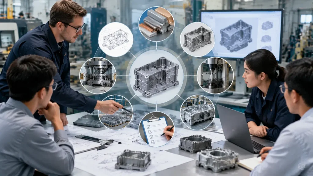
- Define the Required Material System: Start with the mechanical, corrosion, thermal, electrical, weight, environmental, and surface requirements of the component. Determine whether those requirements are best met by a suitable sheet/strip alloy or by an alloy compatible with the proposed die-casting process. If the drawing or application requires steel or stainless steel, conventional high-pressure die casting is generally not a practical route, so sheet-metal processes such as stamping may warrant evaluation depending on the geometry.
- Analyze Part Geometry and Section Variations: Determine whether the component can be created by shearing and bending uniform-thickness sheet metal, or if it requires variable wall sections, internal bosses, and complex 3D profiles.
- Establish Structural and Mechanical Constraints: Review load-bearing, stiffness, impact, fatigue, thermal, and environmental requirements. Compare candidate material systems and geometries using the mechanical properties and manufacturing condition relevant to the actual application rather than assuming that either stamping or die casting is inherently stronger.
- Map the Complete Manufacturing Route: List every post-forming operation required for both options, including deburring, secondary CNC machining, hole tapping, welding, surface finishing, and hardware installation. Calculate unit economics based on the complete route.
- Audit Tooling Capital and Lifetime Program Volumes: Compare the NRE tooling expenditure against projected annual production volumes over the expected lifespan of the program to determine amortization impact per part.
- Evaluate Quality and Risk Factors: Assess tolerance sensitivity, leak-tightness requirements, and surface finish needs. Compare the impact of stamping springback and burrs against casting porosity and warpage.
- Assess Design Maturity: Consider the likelihood of future engineering changes. If the product design is evolving rapidly, choose the manufacturing route and tooling strategy that offers the most manageable revision pathways.
- Request DFM Review and Dual Quotations: Provide detailed 2D drawings and 3D CAD models to qualified manufacturing partners for a comprehensive DFM review and complete route quotation before finalizing process selection.
Frequently Asked Questions
1. Can steel or stainless steel parts be high-pressure die cast?
Conventional high-pressure die casting is generally not a practical commercial route for steel or stainless steel. Their much higher processing temperatures create severe thermal and tooling challenges compared with the non-ferrous alloys commonly used in HPDC. Components requiring steel or stainless steel therefore need a manufacturing route suited to the actual geometry and application requirements, which may include stamping, forging, machining, or other appropriate processes.Where machining is the main alternative, see our metal stamping vs CNC machining comparison.
2. Is die casting always more expensive in tooling cost than metal stamping?
No. Tooling cost depends on part size, geometry, tool architecture, production requirements, cavity or station complexity, and other project-specific factors. A complex multi-station progressive stamping die can require greater tooling investment than a relatively simple die-casting tool, while a simple stamping die may require substantially less investment than a complex casting tool with moving cores or slides.
3. When should a multi-piece stamped assembly be considered for conversion to a single die casting?
Conversion may be worth evaluating when a stamped assembly requires multiple joining operations, substantial assembly labor, numerous fasteners, or creates significant assembly tolerance stack-up. The redesign must still confirm that a suitable casting alloy, cast geometry, mechanical performance, quality requirements, secondary operations, tooling commitment, and complete program economics are appropriate for the application.
4. Does die casting eliminate all secondary machining operations?
No. Die casting can produce near-net-shape components, but some features may still require secondary machining depending on drawing tolerances, surface requirements, sealing interfaces, threads, bores, and other functional requirements. Machining, drilling, tapping, or related secondary operations should therefore be evaluated feature by feature rather than assumed to be either always necessary or completely eliminated.
5. Which process provides better mechanical performance: metal stamping or die casting?
Neither process provides universally superior mechanical performance. Mechanical performance depends on the specific alloy, temper or heat treatment, material condition, section geometry, manufacturing history, defect control, and application loading conditions. Stamped sheet structures and die-cast structures can also use different geometric strategies to achieve stiffness and load-carrying capability, so the comparison should be made using the actual material and component design rather than the process name alone.
Conclusion
Choosing between metal stamping vs die casting requires evaluating material requirements, part geometry, mechanical performance, tooling commitment, secondary operations, assembly requirements, and complete manufacturing-route economics rather than relying on a universal process preference or production-volume threshold.
Metal stamping can be advantageous when the required material is available in suitable sheet, strip, coil, or blank form; the geometry can be produced efficiently through cutting and forming operations; and repeat-production economics support dedicated stamping tooling. Die casting can be advantageous when a suitable casting alloy meets the application requirements and complex three-dimensional geometry, integrated ribs or bosses, or part consolidation provides meaningful functional or manufacturing value.
For OEM buyers, the most reliable decision comes from comparing both complete manufacturing routes using the actual drawing, material and mechanical requirements, quality criteria, expected lifetime quantity, required secondary operations, and project-specific quotations.