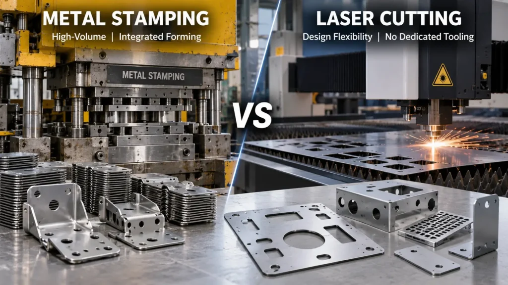
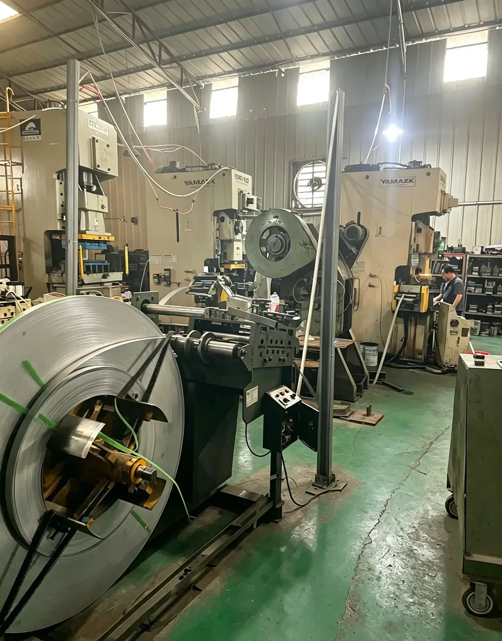
Selecting between metal stamping vs laser cutting for sheet metal components is a critical decision in product development and procurement. Neither process is universally superior; conventional flat-sheet laser cutting prioritizes design agility and avoids dedicated hard tooling, while metal stamping can become advantageous when part geometry, repeat production, integrated forming, and long-term program economics justify dedicated tooling investments.
Evaluating these processes requires looking beyond basic production volumes to examine how part geometry, secondary operations, tooling commitment, edge characteristics, and total manufacturing sequences impact the true cost of a finished component.
Metal Stamping vs Laser Cutting: Quick Comparison
Comparison Factor
Metal Stamping
Laser Cutting
Tooling Investment
Requires dedicated stamping dies with higher upfront tooling cost for repeat production programs.
Avoids dedicated hard tooling, but requires CAD/CAM programming, nesting, machine setup, and material preparation.
Production Volume
Best suited for medium to high-volume production with stable part designs and repeat demand.
Better suited for prototypes, low-volume production, and products with frequent design changes.
Unit Cost at Volume
Lower per-part cost after tooling investment is distributed across larger production quantities.
Unit cost depends on machine time, material utilization, nesting efficiency, and batch size.
Production Speed
Extremely fast cycle times after tooling is completed and production is optimized.
Flexible production speed but generally less suitable for very high-volume repeat production.
Design Flexibility
Design changes after die completion may require tooling modification and additional engineering time.
High flexibility because changes can be made directly through CAD file and cutting program updates.
Geometry Capability
Can combine cutting, piercing, bending, forming, and coining operations in stamping tooling.
Primarily creates flat 2D profiles; additional forming operations are required for 3D features.
Secondary Operations
Multiple operations can often be integrated into progressive or compound stamping processes.
May require additional bending, deburring, welding, or assembly after cutting.
Edge Characteristics
Produces mechanically sheared edges with rollover, burnished zone, fracture zone, and possible burr.
Produces thermal-cut edges that may include heat-affected zones, dross, or oxidation depending on settings.
Best Applications
Brackets, clips, housings, electrical parts, and repeat OEM sheet metal components.
Prototypes, customized sheet metal parts, short production runs, and design validation.
Dedicated Tooling Investment
Metal Stamping: Requires dedicated hard tooling, such as progressive or compound stamping dies engineered for a specific part geometry. Involves higher initial Non-Recurring Engineering (NRE) costs.
Laser Cutting: Laser cutting avoids dedicated part-specific hard tooling, while each job still requires CAD/CAM programming, nesting, machine setup, and material handling.
Setup and Programming
Metal Stamping: Setup requires physical die mounting, press alignment, coil loading, and sensor calibration before a production run begins.
Laser Cutting: Setup focuses on uploading digital nest files, setting beam parameters, installing nozzle tips, adjusting assist gas pressures, and staging sheet material.
Unit Economics
Metal Stamping: Delivers lower variable costs per part as production volumes increase, as the upfront hard tooling investment is amortized over a larger quantity of parts.
Laser Cutting: Laser cutting continues to incur machine-time and consumable costs for each part, although actual unit cost can change with batch size, nesting efficiency, setup amortization, automation, and material utilization.
Flat vs Formed Geometry
Metal Stamping: Capable of executing complex 2D profile cutting and 3D forming operations—such as bends, draws, extrusions, and coinings—within the same tooling system.
Laser Cutting: Conventional flat-sheet laser cutting is primarily a two-dimensional profile cutting process. Three-dimensional features must be introduced through downstream operations.
Secondary Operations
Metal Stamping: Can consolidate multiple cutting, piercing, forming, and coining steps into integrated press strokes or across consecutive die stations, reducing manual handling.
Laser Cutting: When a finished component requires bends, formed features, hardware, or deburring, laser cutting is often one step in a broader multi-stage fabrication sequence.
Design-Change Flexibility
Metal Stamping: Engineering revisions after hard tooling is completed require physical modifications to tool steel, which can incur additional costs and production lead time.
Laser Cutting: High design flexibility. Revisions are executed digitally by modifying the CAD model and updating the laser cutting toolpaths.
Edge Characteristics
Metal Stamping: Mechanically sheared edges exhibit a distinct cross-sectional profile featuring a rollover zone, burnished shear band, fracture zone, and exit burr.
Laser Cutting: Thermal-cut edges feature narrow kerfs and vertical cut lines, but may display a heat-affected region, micro-dross, or oxidation depending on assist gas selection.
Production Scalability
Metal Stamping: Once suitable tooling is running, stamping can provide high throughput for repeat production, although actual production rate depends on part geometry, die design, material behavior, press capability, and feeding requirements.
Laser Cutting: Scalability is limited by total cut path length, material thickness, and laser head movement speed across individual sheets.
Understanding the Core Process Differences
Comparing metal stamping vs laser cutting begins with understanding how each technology physically manipulates raw sheet metal to achieve a final component geometry.
How Laser Cutting Works for Sheet Metal
Conventional flat-sheet laser cutting is a non-contact, thermal subtractive manufacturing process. A high-power laser beam—typically generated via fiber or CO2 sources—is focused onto a metal sheet to locally melt, vaporize, or burn away material along a programmed two-dimensional path. An assist gas, such as nitrogen or oxygen, is blown coaxially through the cutting nozzle to eject the molten slag from the kerf.
The cutting path is generated digitally from CAD/CAM data, allowing the cutting head to follow programmed two-dimensional profiles without custom-shaped cutting edges. This makes conventional flat-sheet laser cutting ideal for complex 2D outer profiles, intricate internal cutouts, and rapid geometry changes. However, the process remains inherently focused on profile cutting in a single plane.
How Metal Stamping Works for Sheet Metal
Metal stamping is a mechanical, deformative, and shearing manufacturing process. Sheet metal stock, often supplied as continuous coil or flat blanks, is positioned inside a mechanical or hydraulic press between two custom-engineered steel tool components: a punch and a die. When the press cycles, substantial mechanical force drives the punch into the die cavity, shearing, bending, stretching, or compressing the sheet metal into shape.
Unlike pure profile cutting, stamping can execute both cutting operations (such as blanking, piercing, and notch-shearing) and forming operations (such as bending, flanging, coining, embossing, and deep drawing). Dedicated stamping tooling can integrate multiple operations. In a progressive die, consecutive stations may perform piercing, forming, bending, or other operations as the strip advances through the tool.
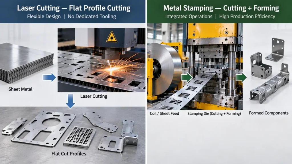
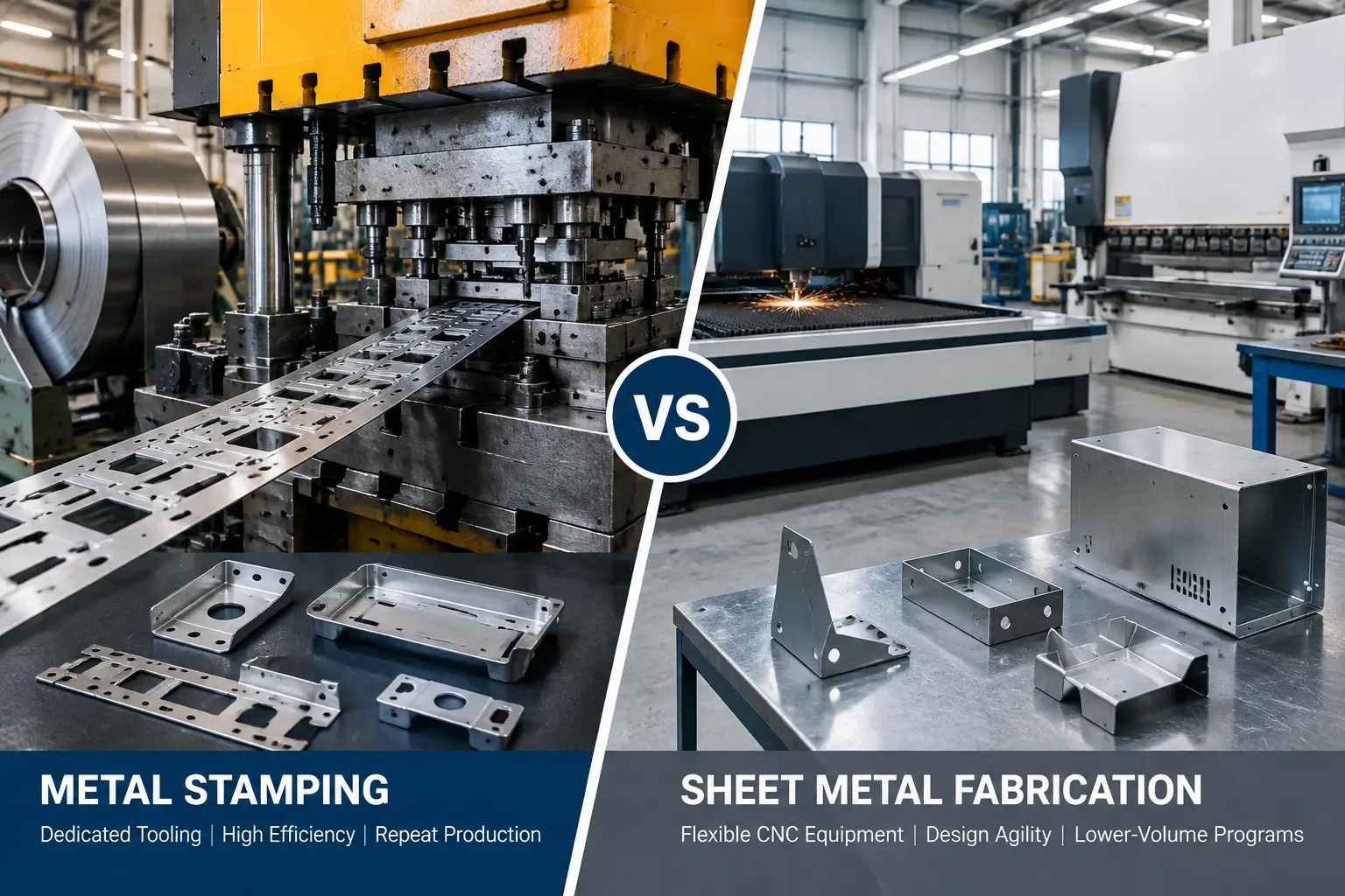
Conventional flat-sheet laser cutting creates cut profiles, while stamping can integrate cutting and forming operations through dedicated tooling.
Tooling Investment vs. Unit Economics
The economic choice between laser cutting or stamping for sheet metal parts relies heavily on how upfront investments balance against ongoing operational expenses over a product’s lifespan.
Dedicated Stamping Tooling vs. Laser Programming and Setup
Cost Factor
Metal Stamping
Laser Cutting
Initial Investment
Higher upfront tooling cost due to dedicated dies and engineering development
Lower initial investment without dedicated hard tooling
Setup Cost
Die installation, press setup, material feeding, and process validation
CAD/CAM programming, nesting, machine setup, and material preparation
Unit Cost at Low Volume
Higher because tooling cost is distributed over fewer parts
Usually competitive because no dedicated tooling investment is required
Unit Cost at High Volume
Lower because tooling cost is amortized over large production quantities
Continues to include machine time, labor, and consumable costs
Long-Term Economics
Strong advantage for stable repeat-production programs
Better suited for flexible production and changing designs
Metal stamping relies on dedicated hard tooling. Designing, machining, heat-treating, and qualifying a high-precision progressive or compound die requires upfront capital allocation and engineering lead time. This Non-Recurring Engineering (NRE) cost establishes a hard physical asset dedicated solely to one part geometry.
Conversely, laser cutting avoids dedicated part-specific hard tooling, drastically lowering the initial financial barrier to entry. However, laser cutting is not completely free of setup expenses. Every job requires CAD/CAM file processing, nesting optimization, material staging, beam focusing, nozzle alignment, and test cutting. Instead of investing in physical steel, laser cutting incurs operational setup costs every time a batch is scheduled.
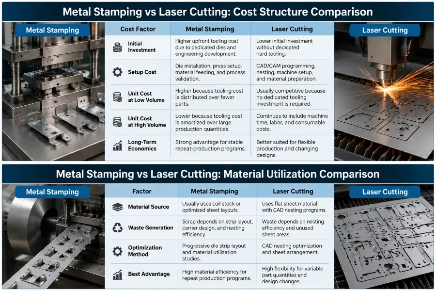
Metal stamping requires higher upfront tooling investment, while laser cutting avoids dedicated dies but continues to incur machine and setup costs during production.
What Actually Drives Unit Cost?
Understanding unit cost requires breaking down how each process accrues expenses during execution:
Laser Cutting Unit Costs: Governed primarily by machine run time, which scales directly with total cut path length, material thickness, assist gas consumption (nitrogen vs. oxygen), and power requirements. Laser cutting continues to incur machine-time and consumable costs for each part, although actual unit cost can change with batch size, nesting efficiency, setup amortization, automation, and material utilization.
Metal Stamping Unit Costs: Driven by raw material strip utilization and press cycle rates. Once a die is installed and aligned, a press operates rapidly, completing multiple cutting and forming operations simultaneously. The variable cost per stamped component can become lower because machine runtime per part is minimal, and the initial NRE tooling expense is spread across the entire production run.
How to Evaluate the Economic Break-Even Point
Sourcing teams often look for a universal volume threshold to dictate process selection. In reality, no fixed crossover quantity exists. Determining when metal stamping becomes more cost-effective than laser cutting requires evaluating project-specific variables using a structured break-even framework.
The conceptual framework for evaluating the economic break-even point is expressed as:
Break-Even Quantity = (Stamping Tooling Cost – Laser Setup Cost) / (Laser Unit Cost – Stamping Unit Cost)
In this framework:
Stamping Tooling Cost includes the total NRE expenditure to design, fabricate, and qualify the custom die set.
Laser Setup Cost accounts for CAD/CAM programming, nesting, machine setup, and material handling preparations.
Laser Unit Cost reflects the per-part cost of laser machine time, assist gas, labor, and raw sheet material.
Stamping Unit Cost reflects the per-part cost of raw coil stock, press operating time, and ongoing die maintenance.
Because every project has a different combination of geometry, material, tooling complexity, cutting time, secondary operations, and quality requirements, generic crossover quantities are unreliable.
Procurement decisions should always rely on project-specific quotations that account for expected lifetime program quantities rather than relying on arbitrary volume estimates or focusing solely on the initial purchase order.
Geometry and Forming: Flat Profiles vs. Integrated Features
Part geometry is often the primary technical factor determining process selection. A core engineering difference between these two manufacturing routes lies in how flat profiles are transformed into functional 3D components.
When a Flat Laser-Cut Profile May Be Enough
For components that remain entirely flat throughout their functional life—such as shim plates, flat mounting plates, decorative panels, flat brackets, and wear plates—conventional flat-sheet laser cutting provides a direct, highly efficient path from CAD file to finished part. When no secondary forming, bending, or hardware insertion is required, laser cutting eliminates the need for dedicated forming dies without introducing multi-step manufacturing complexity.
When the Part Requires Bends and Formed Features
When a sheet metal component includes 3D features—such as flanges, stiffening ribs, countersinks, louvers, drawn bosses, or coined thread relief channels—those features generally require additional forming or secondary operations after conventional flat-sheet laser cutting.
To complete a formed part starting from a laser-cut blank, the component must be transferred to secondary operations. Bends and flanges are typically added using a CNC press brake, which requires manual or robotic manipulation of each individual part against dedicated press brake tooling. Features like countersinks, tapped holes, or clinching hardware require additional drilling, tapping, or insertion steps.
Comparing Multi-Step Fabrication with Integrated Stamping
When evaluating total production economics, engineers must compare the complete manufacturing sequence of both routes rather than looking solely at the primary cutting operation.
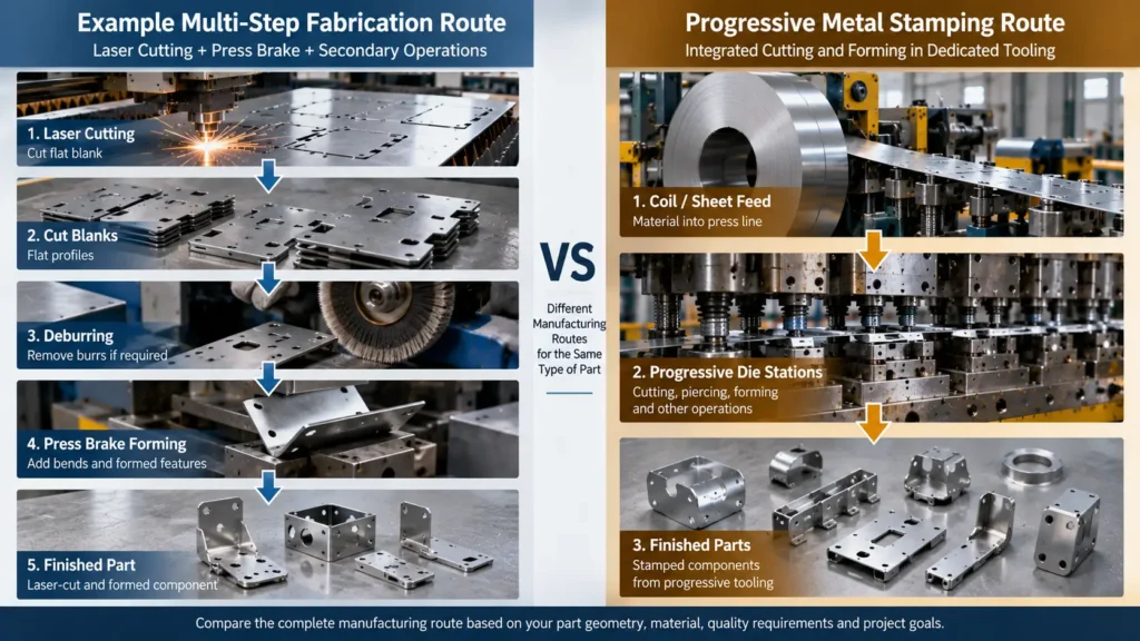
For formed parts, buyers should compare the complete fabrication route with the complete stamping route, including any required secondary operations.
Offloading and deburring flat blanks to remove micro-tabs or edge dross.
Transferring blanks to a CNC press brake for multi-hit sequential bending.
Executing secondary operations, such as hardware clinching, spot welding, or tapping.
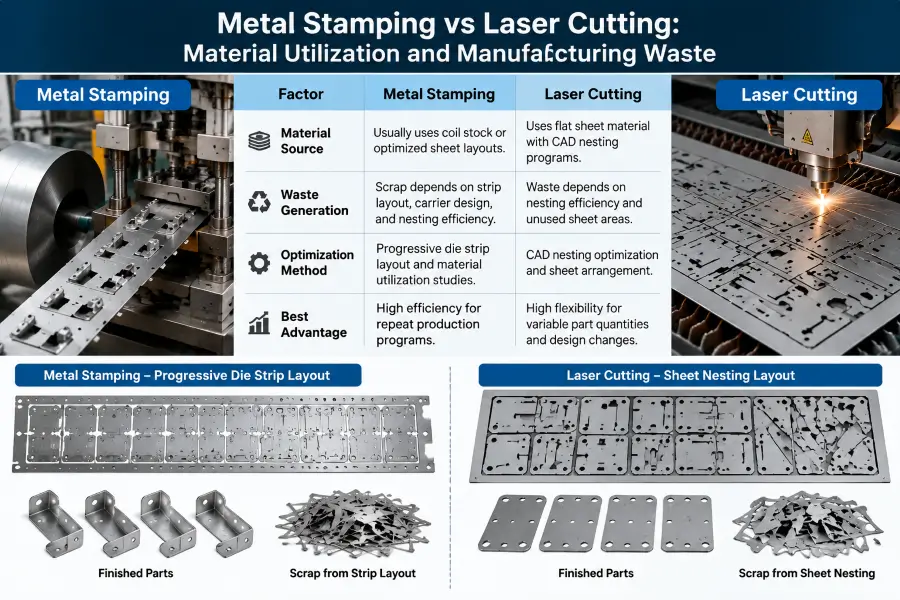
Material utilization depends on production strategy: stamping uses optimized strip layouts for repeat production, while laser cutting relies on CAD nesting flexibility for sheet utilization.
Material Utilization and Manufacturing Waste
Factor
Metal Stamping
Laser Cutting
Material Source
Usually uses coil stock or optimized sheet layouts
Uses flat sheet material with CAD nesting
Waste Generation
Scrap depends on strip layout, carrier design, and nesting efficiency
Waste depends on nesting efficiency and unused sheet areas
Optimization Method
Progressive die strip layout and material utilization studies
CAD nesting optimization and sheet arrangement
Best Advantage
High efficiency for repeat production programs
High flexibility for changing part quantities
In contrast, dedicated stamping tooling can integrate these disparate operations within dedicated tooling:
Coil stock is automatically fed into the stamping press.
Consecutive die stations perform piercing, pilot-pin positioning, coining, embossing, bending, and flanging in synchronized press strokes.
Completed 3D components are severed from the carrier strip and ejected directly from the press.
While the multi-step fabrication route avoids hard tooling investments, the cumulative labor, machine time, part handling, and work-in-progress inventory of secondary operations can significantly elevate total unit cost. Stamping integrates these geometric transformations directly into the tooling, exchanging upfront NRE for a streamlined production workflow.
Edge Characteristics, Tolerances and Material Behavior
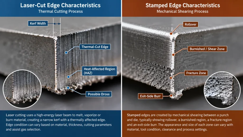
Laser cutting creates a thermal-cut edge, while stamping creates a mechanically sheared edge with rollover, burnished, fracture and burr regions.
Both laser cutting and metal stamping alter the physical edge structure of sheet metal, but they do so through completely different mechanical and thermal mechanisms.
Laser-Cut Edge Characteristics
Laser cutting is a thermal separation process. As the focused beam melts or vaporizes material along the kerf, the edge is subjected to rapid localized heating and cooling. This thermal dynamic creates specific edge characteristics:
Heat-Affected Region: Localized heating can modify the microstructure or hardness near the cut edge in some materials, depending on alloy, thickness, cutting parameters, and thermal input.
Edge Oxidation: When oxygen is used as an assist gas to boost cutting speed in carbon steel, a thin oxide scale forms along the cut edge. This oxide layer must often be removed prior to painting or powder coating to ensure proper surface adhesion. Nitrogen assist gas is commonly used when minimizing oxidation at the cut edge is important, although final edge condition still depends on material and cutting parameters.
Dross and Micro-Joint Marks: Depending on material thickness, laser power calibration, and gas pressure, minor slag or dross may adhere to the bottom edge of the cut. Additionally, if parts are nested with micro-tabs to keep them secured within the sheet skeleton, tiny tab remnants will remain on the edge after removal.
Stamped Edge Characteristics
Metal stamping relies on mechanical shear forces exceeding the ultimate tensile strength of the material. A mechanically sheared stamped edge commonly exhibits rollover, a burnished/sheared region, a fracture region, and an exit-side burr, although their proportions vary with material, clearance, tool condition, and process settings:
Rollover Zone: A smooth, rounded radius along the top edge where the material plastically deforms before shearing begins.
Burnished Zone (Shear Band): A straight, vertical, and smooth section of the edge created as the punch penetrates the material.
Fracture Zone (Break-off): A rougher, slightly angled region beneath the shear band where the metal fractures naturally under stress.
Burr: A thin material overhang along the exit edge of the punch, the size of which is dictated by punch-to-die clearance and tool wear.
Understanding these mechanical zones allows engineers to orient critical functional features—such as press-fit pin holes or mating sliding surfaces—to ensure the smooth burnished zone aligns with functional requirements.
Why Tolerance Capability Must Be Evaluated by Feature
Claiming that one process is universally more accurate than the other oversimplifies real-world manufacturing conditions. Precision depends on specific feature geometries, material thickness, machine capability, and tooling design:
Laser Cutting Tolerances: Laser cutting does not rely on a contacting cutting edge such as a punch, but dimensional capability still depends on machine condition, optics, focus, material behavior, thermal effects, and process parameters. Thermal distortion can occur on thin sheets with tightly spaced cutouts, and secondary press brake bending introduces positional variation dependent on operator skill and material springback.
Stamping Tolerances: Extremely repeatable across large batch runs for both flat cutouts and 3D formed features because every dimension is physically fixed within hardened tool steel. However, stamping tolerances are influenced by punch-to-die clearance, tool wear over time, press deflection, and batch-to-batch variations in material thickness and hardness.
Dimensional capabilities must always be validated against project-specific engineering drawings, material specifications, and quality acceptance criteria.
Quality Control Considerations
Quality Factor
Metal Stamping
Laser Cutting
Process Control
Tool condition, press parameters, material consistency
Laser parameters, focus, gas pressure, thermal control
Dimensional Verification
Fixtures, gauges, CMM inspection
Dimensional inspection, CMM, profile measurement
Repeatability
Strong for stable tooling and production conditions
Strong for controlled laser programming
Main Risk
Tool wear and material variation
Thermal effects and secondary forming variation
Design Flexibility and Engineering Changes
A product’s stage in its commercial lifecycle plays a central role in selecting between metal stamping vs laser cutting.
During early product development, engineering changes are common. Features may be shifted, hole diameters adjusted, or flange lengths modified based on functional testing.
Laser cutting offers significant design flexibility for evolving components. Because cutting toolpaths are controlled digitally, an engineering revision requires updating the 3D CAD model, regenerating the CAM nest file, and loading the new program into the laser controller. The physical impact on production hardware is minimal, making laser cutting highly adaptable during iterative design phases.
In metal stamping, post-tooling engineering changes carry far greater operational consequences. Once hardened tool steel die blocks, punches, and stripper plates are built and qualified, dimensional revisions require modifying physical tooling assets.
Minor revisions—such as enlarging a pierced hole—may only require re-grinding or replacing a standard punch insert. Major revisions can require re-machining, replacing die inserts, or redesigning one or more tooling stations. This results in additional NRE expense, extended production downtime, and project delays.
For this reason, committing to custom metal stamping tooling is most prudent when the component design is stabilized, fully tested, and verified.
From Laser-Cut Prototype to Stamped Production Part
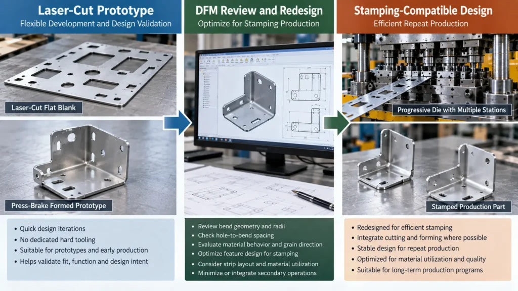
A laser-cut and formed prototype may require DFM changes before the part can be produced efficiently with dedicated stamping tooling.
Rather than viewing metal stamping and laser cutting as mutually exclusive routes, OEM engineering teams frequently use both processes sequentially across a product’s lifecycle.
During initial development, validation, and early bridge-production phases, components can be produced using laser cutting paired with secondary press brake forming. This allows the team to build functional prototypes, conduct physical testing, satisfy initial market launch requirements, and refine the component design without risking capital on custom hard tooling.
As market demand grows and the product design matures, the program may reach a point where cumulative multi-step fabrication costs and throughput limits justify transitioning to dedicated metal stamping.
DFM Review Before Committing to Stamping Tooling
Converting a component designed for laser cutting and press brake bending into a progressive metal stamping part is rarely a direct, one-to-one swap. Because laser cutting and stamping use completely different cutting and forming physics, the part geometry must undergo a thorough Design for Manufacturability (DFM) review.
Key DFM considerations when transitioning from laser fabrication to stamping include:
Bend Radii and Material Behavior: Bend radius, material thickness, alloy, temper, grain direction, and springback must be reviewed when converting a fabricated design to stamping.
Hole-to-Bend Relief Clearances: Pierced features located too close to a bend line may distort during press brake forming or progressive die bending. Adding relief notches or adjusting feature spacing can help control feature distortion.
Flat Blank Layout and Web Clearance: Stamping progressive dies require continuous progression webs to carry the part between stations. Features may need minor adjustments to facilitate efficient strip layout, maximize material utilization, and ensure robust carrier tabs.
Feature Integration: Opportunities to integrate formed features or reduce separate secondary operations should be evaluated before the final die design is frozen.
Executing a comprehensive DFM review before cutting tool steel ensures the component can be stamped efficiently, reliably, and cost-effectively over the program’s lifecycle.
When Laser Cutting Is Usually the Better Choice
Conventional flat-sheet laser cutting—frequently paired with secondary press brake forming—is typically the more appropriate manufacturing route under the following project conditions:
The component is in a prototype, EVT/DVT, or early commercialization phase where engineering revisions remain likely.
Expected program volumes are limited, making it difficult to justify or amortize the upfront NRE cost of custom hard tooling.
The part geometry consists entirely of flat, two-dimensional cut profiles without 3D formed features.
Shorter pre-production preparation may be possible because dedicated stamping-die design and fabrication are not required.
Capital budget constraints prioritize minimal upfront investment over long-term per-part unit savings.
When Metal Stamping Is Usually the Better Choice
Metal stamping is typically the more effective manufacturing route when project parameters align with the following engineering criteria:
The component design is mature, stabilized, and verified, minimizing the risk of post-tooling engineering modifications.
Lifetime program quantities and repeat production orders are sufficient to amortize dedicated stamping die investments.
The finished part requires complex 3D formed features—such as bends, drawn cups, louvers, or coined details—that can be integrated into a unified tooling system.
Project economics favor amortizing dedicated tooling across repeat production and integrating operations where practical.
High production throughput and strict batch-to-batch dimension repeatability are required to satisfy high-volume assembly schedules.
Metal Stamping vs Laser Cutting: How OEM Buyers Should Decide
To select the most practical manufacturing route for a custom sheet metal component, sourcing and engineering teams can follow a structured six-step decision framework.
Step 1: Evaluate the Part Geometry
Analyze the CAD drawing. Is the part a purely flat two-dimensional profile, or does it incorporate 3D bends, flanges, countersinks, and formed features? If the component requires forming, identify whether those features can be integrated into progressive tooling or if they must be executed through multi-step press brake fabrication.
Step 2: Estimate Lifetime Program Quantity
Look beyond the initial purchase order. Calculate total expected demand across the anticipated program lifecycle. Evaluating lifetime volume provides a clear view of how upfront tooling capital will amortize over time.
Step 3: Map the Complete Manufacturing Sequence
Compare the complete stamping production route with the complete laser-cut fabrication route, including any required forming, deburring, hardware insertion, machining, welding, inspection, or other secondary operations.
Step 4: Compare Total Program Economics
Request comprehensive quotes for both manufacturing routes. Calculate total program expenditure by combining initial setup/NRE costs with unit prices multiplied by lifetime volume:
Total Program Cost = Initial NRE/Setup Investment + (Unit Price × Total Lifetime Quantity)
Use the comparison to determine which route provides the more suitable total manufacturing economics for the project.
Step 5: Evaluate Design Stability and Engineering-Change Risk
Assess the maturity of the component design. If the part is subject to upcoming mating-assembly revisions or ongoing field testing, laser cutting minimizes capital exposure. If the design is frozen and validated, committing to metal stamping hard tooling becomes economically viable.
Step 6: Request a DFM Review Before Hard Tooling
Before releasing funds for hard tooling or finalizing purchase orders, submit component drawings to an experienced manufacturing partner for a thorough Design for Manufacturability review. A detailed DFM evaluation identifies geometric optimizations, material utilization improvements, and tooling considerations that protect project budgets and ensure long-term manufacturing success.
Frequently Asked Questions
1. Is laser cutting always faster than metal stamping for sheet metal parts?
Not necessarily. Laser cutting offers faster initial setup and eliminates tooling lead time, allowing first parts to be produced quickly from a CAD file. However, metal stamping can provide substantially higher throughput for suitable repeat-production parts once dedicated tooling is running.
2. Does laser cutting eliminate all tooling and setup costs?
No. While laser cutting avoids dedicated hard forming dies (NRE), it is not completely free of setup expenses. Every production run requires CAD/CAM programming, nesting optimization, machine setup, nozzle positioning, assist gas adjustment, and material handling preparations, which are reflected in the operational machine rate.
3. Why do laser-cut sheet metal parts sometimes require press brake operations?
Conventional flat-sheet laser cutting primarily creates two-dimensional cut profiles. If a finished component features 3D geometries—such as 90-degree bends, mounting flanges, or stiffening channels—the flat laser-cut blank must undergo secondary bending operations on a CNC press brake to achieve its final shape.
4. Can a laser-cut and bent prototype be converted to progressive metal stamping?
Yes. A laser-cut and press-brake-formed prototype can potentially be redesigned for progressive stamping, but the conversion requires DFM review to adapt bend radii, hole-to-bend relief clearances, material grain orientation, and feature spacing to suit high-speed progressive die tooling.
5. Which process produces better edge quality for sheet metal parts?
Neither process produces universally superior edges; they create fundamentally different edge structures. Laser cutting produces a narrow, thermal-cut kerf that may feature a heat-affected region or oxide scale depending on assist gas selection. Metal stamping produces a mechanically sheared edge characterized by a rollover zone, smooth burnished shear band, fracture zone, and exit burr. Edge suitability depends on part function and downstream finishing requirements.
Conclusion
Choosing between metal stamping vs laser cutting requires evaluating part geometry, design maturity, secondary operations, tooling commitment, production requirements, and total program economics rather than relying on a universal volume threshold.
Conventional flat-sheet laser cutting can provide valuable flexibility when designs are evolving or dedicated hard tooling is difficult to justify. Metal stamping can become advantageous when the geometry is suitable for dedicated tooling, the design is stable, multiple cutting or forming operations can be integrated, and repeat-production economics support the tooling investment.
For OEM buyers, the most reliable decision comes from comparing the complete manufacturing route for both options using the actual drawing, material specification, quality requirements, expected lifetime quantity, and project-specific quotations.
If you are evaluating a new sheet metal part or considering whether a laser-cut and formed component could be redesigned for stamping, request a DFM review and project quotation from Metal Stamp Factory.