Founder of Metal Stamp Factory with more than 25 years of hands-on experience in tooling development, metal stamping, and OEM production.
(Metal Stamp Factory was established in 2014 in Xiamen, China.)
What Are Stamped Electrical Contacts and Connector Terminals?
Custom stamped electrical contacts and connector terminals are conductive sheet- or strip-metal components made to customer drawings for electrical connection, mating, retention, or termination functions in OEM assemblies. Depending on the design, they may be produced by conventional stamping or progressive die stamping.
Electrical contacts and connector terminals are one specialized category within the broader field of electrical metal stamping parts, which also includes structural brackets, housings, heat-management components, and other stamped electrical hardware.
Typical stamping operations may include blanking, piercing, bending, offset forming, and other drawing-defined forming steps. Manufacturability depends on the material, temper or condition, thickness, local geometry, edge condition, surface-finish requirements, and the way the part interfaces with the final assembly.
Electrical Contacts vs. Connector Terminals: Where They Overlap
While frequently referenced together, electrical contacts and connector terminals serve distinct structural and functional roles within an assembly:
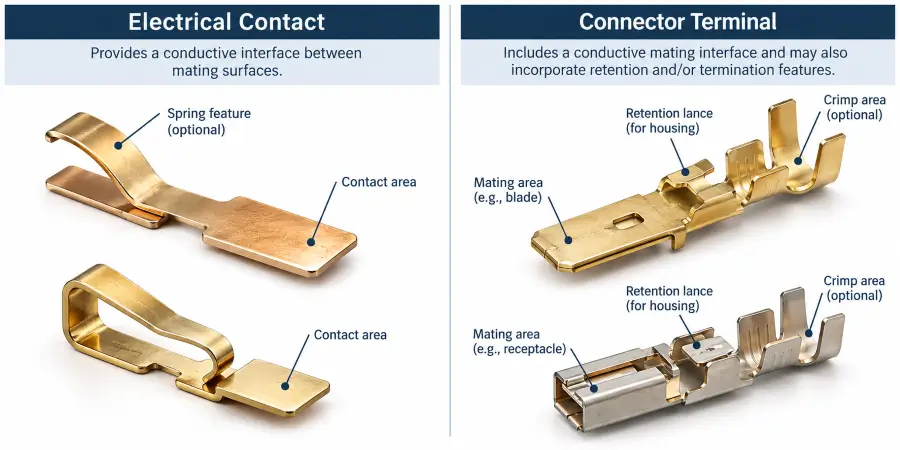
- Electrical Contact: A conductive interface component designed specifically to transfer electrical current or signals between two mating surfaces. Depending on the application, contacts may include flat contact areas, formed pads, or spring features that create or maintain the intended mating interface.
- Connector Terminal: A termination and mating component that provides the electrical connection while frequently incorporating secondary mechanical features—such as retention lances, locking tabs, or crimp barrels—designed to secure the component inside a connector housing or onto a conductor.
Not every electrical contact functions as a connector terminal, and not every connector terminal serves as the primary contact interface. In custom stamping, both are reviewed using many of the same stamping considerations, including material condition, formability, bend geometry, edge condition, and tooling strategy.
Common Stamped Contact and Terminal Geometries
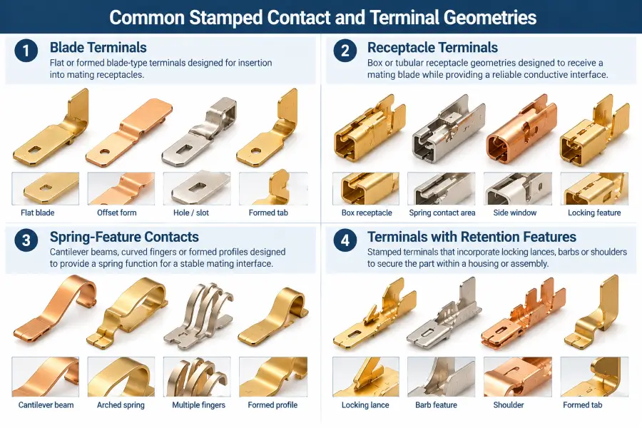
Custom stamped contacts and terminals can be configured into a wide variety of shapes depending on the spatial and functional constraints of the application:
- Blade Terminals: Flat or slightly formed conductive tabs designed to insert into matching receptacles or spring contacts.
- Receptacle Terminals: Box-formed or socket-like geometries designed to receive a mating blade or contact feature.
- Spring-Contact Features: Integrated cantilever beams, curved fingers, or arched profiles designed to deflect during mating and recover elastically within the intended operating range.
- Terminals with Retention Features: Components incorporating locking lances, barbs, or shoulders to anchor the stamped part firmly within a housing cavity.
| Geometry Type | Primary Function | Typical Application Interface |
|---|---|---|
| Blade Terminals | Mating electrical connection | Receptacle sockets, mating spring contacts |
| Receptacle Terminals | Female mating and wiping interface | Insertion blade terminals, interface pins |
| Spring-Contact Features | Elastic mating or contact function | Sliding interfaces, switch contacts, contact pads |
| Retaining Terminals | Housing retention or assembly positioning | Connector housings and electromechanical sub-assemblies |
Material Selection for Stamped Contacts and Terminals
Metal stamping material selection for custom stamped electrical contacts and connector terminals requires balancing electrical, mechanical, and manufacturing parameters.
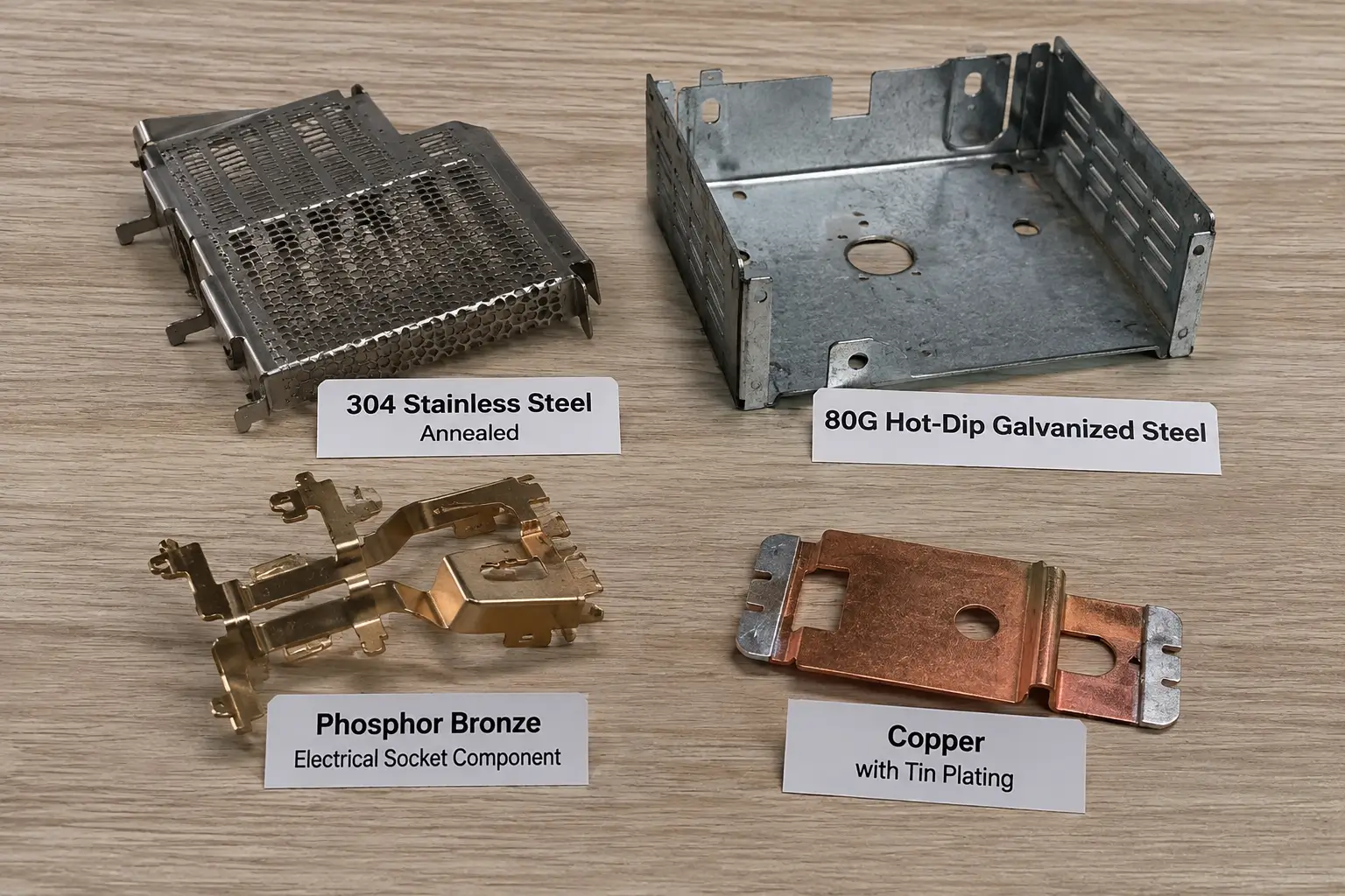
Copper
Copper may be specified where high electrical conductivity is important. Its suitability still depends on the required geometry, thickness, mechanical loading, material condition, and whether the part includes spring or retention features.
Brass
Brass can provide a useful balance of formability, mechanical strength, corrosion behavior, and electrical conductivity for many stamped terminal and contact designs.
Phosphor Bronze
Phosphor bronze is commonly considered for stamped contact applications where conductivity, strength, formability, and elastic behavior must be balanced. Whether it is suitable depends on the drawing, temper, thickness, forming severity, and functional requirements.
Conductivity, Strength and Elastic Behavior Must Be Balanced
Material selection should not be based on a single property in isolation. The copper alloy properties for connectors and contacts provide useful background for understanding these trade-offs:
- Conductivity vs. Strength: Higher-conductivity materials may offer electrical advantages, but the finished part may also need sufficient strength and dimensional stability for forming, mating, retention, or assembly.
- Elastic Behavior: Where a design includes spring deflection, the specified material and geometry must provide the required elastic response within the customer-defined functional limits.
The electrical performance requirements—such as operating current, allowable resistance, temperature rise, or system performance—should come from the customer or applicable engineering specification. Metal Stamp Factory evaluates the manufacturability of the specified geometry and material against these parameters.
How Material Temper Affects Forming and Contact Features
Specifying the alloy alone may not provide enough information for tooling review. Temper designations for copper and copper alloys provide standardized terminology for material condition. Temper can significantly affect how strip stock responds during stamping and forming:
- Formability vs. Elastic Response: Softer conditions may tolerate more severe forming, while harder conditions can increase springback and may require different bend radii or forming strategies.
- Local Work Hardening: Forming can introduce local work hardening in bend and formed regions, and its significance depends on the alloy, temper, strain level, and forming sequence.
From Our Stamping Experience: Contact Geometry and Material Must Be Reviewed Together
From a stamping and tooling perspective, custom stamped electrical contacts and connector terminals should not be evaluated only by alloy or thickness.
Material condition, bend geometry, pierced features, mating areas, retention features, burr direction, forming sequence, and surface-finish requirements can all affect manufacturability.
Metal Stamp Factory’s in-house tooling team handles custom stamping die design and assembly after the customer confirms the part drawing and project requirements. Typical progressive die development takes 35–40 days, depending on part complexity and tooling scope.
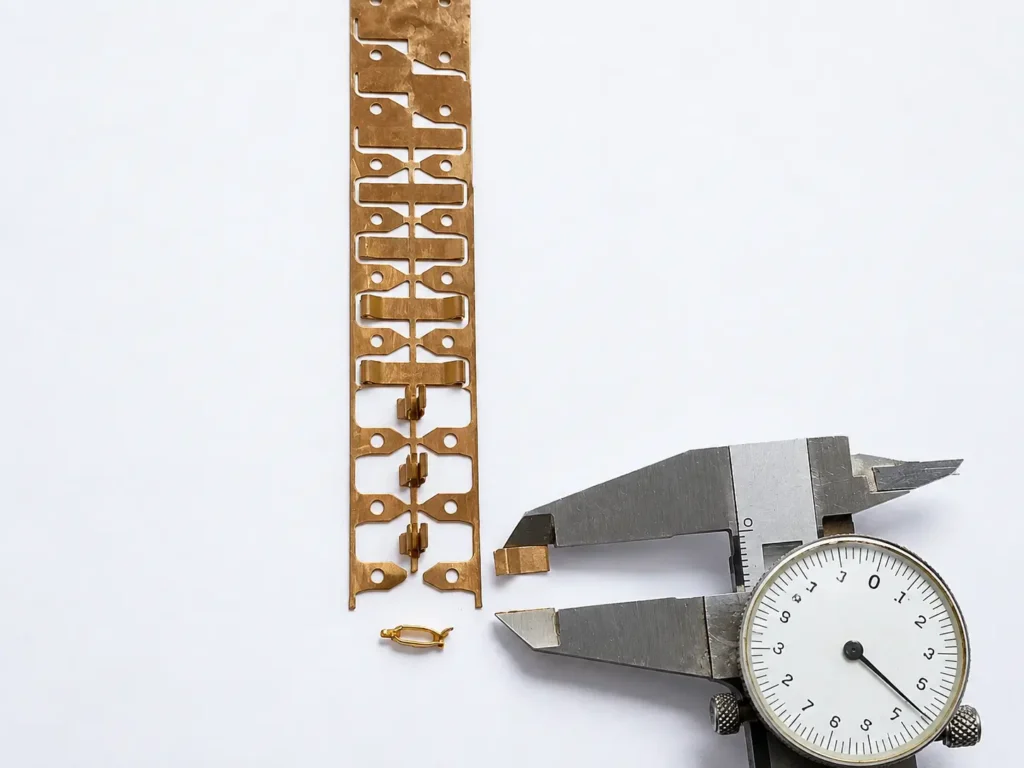
The featured phosphor bronze strip is a real production example of progressive-die stamped electrical contact components. The production image and dimensional inspection evidence illustrate how material, strip progression, formed geometry, and drawing-critical dimensions are considered together during manufacturing.
Mating Surfaces, Spring Features and Functional Geometry
The functional geometry of a stamped contact should be reviewed in relation to the mating part and assembly:
- Mating Surfaces: Drawing-defined contact areas may require controlled position, form, and edge condition so they engage the mating component as intended.
- Spring Features: Cantilever beams, deflection arms, and arched profiles should be defined with suitable geometry for the specified material and expected deflection range. Contact-force requirements should come from the customer or applicable engineering specification.
Crimp and Retention Features
Many connector terminals incorporate features designed for wire termination or housing retention:
- Crimp Barrel Geometry: Open or closed barrel features may be included where the terminal is later crimped to a conductor during downstream assembly.
- Retention Lances: Formed barbs or tabs may engage corresponding housing features to help retain the terminal after insertion.
- Feature Location: These features should be positioned and dimensioned according to the customer drawing so they align with the intended downstream assembly.
Geometry and Design-for-Stamping Considerations
Design-for-manufacturing review for custom stamped contacts and terminals focuses on whether the specified geometry can be formed consistently. The broader metal stamping design guidelines provide additional context for bend radii, feature spacing, and forming-related DFM considerations:
- Bend Radius Relative to Thickness: Tight bends in harder tempers increase outer-fiber tensile stress, requiring appropriate bend radii to prevent tearing.
- Feature Proximity to Bends: Pierced holes, slots, or locking features located close to a bend line may distort during forming and should be reviewed with the bend sequence.
- Local Geometry Control: Coining operations may be utilized for local geometry control, local flattening, feature definition, or profile and thickness modification in specific contact zones.
Progressive Die Stamping for Connector Terminals and Contacts
Progressive die stamping can be an efficient manufacturing option for suitable medium- and high-volume electrical contact and connector-terminal designs.
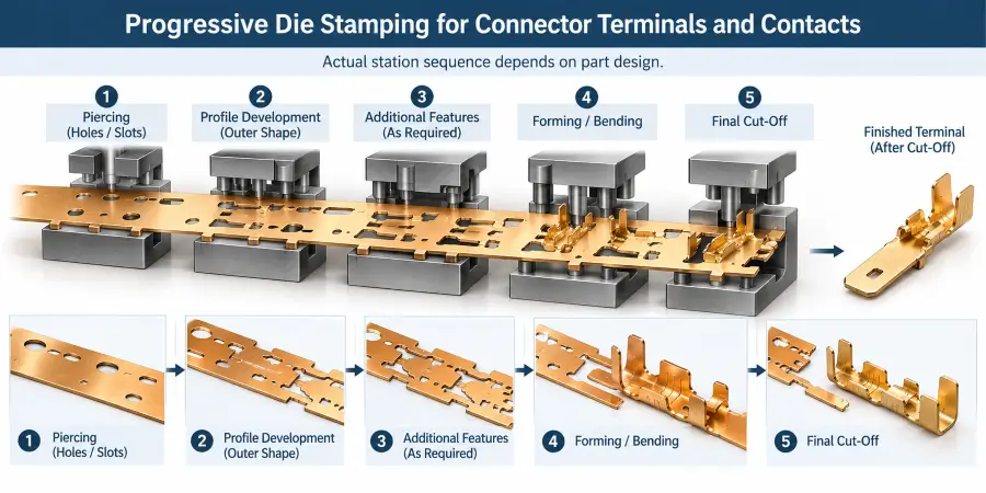
In a progressive die, strip material advances through multiple stations, with different operations performed at successive positions. Depending on the component, the sequence may include:
For a deeper look at terminal-specific tooling decisions, see our guide to strip layout and station sequencing for electrical terminals.
- Piercing: Producing holes, slots, or other internal features where required.
- Profile Development: Creating the external shape while maintaining the part on the carrier strip.
- Additional Features: Adding drawing-required features such as local forms or coining where needed.
- Forming and Bending: Producing offsets, bends, or other formed geometry.
- Final Cut-Off: Separating the finished terminal or contact from the strip.
Tooling strategy is selected based on part geometry, material specifications, tolerance requirements, and projected production volume.
Burr Direction and Edge Quality on Functional Areas
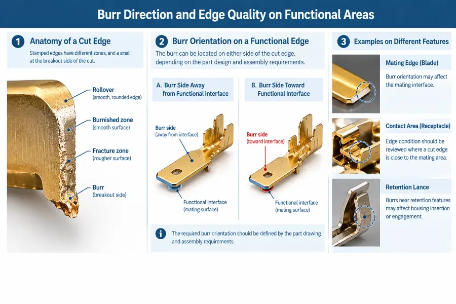
Blanking and piercing naturally create characteristic edge zones and a mechanical burr on the exit side of the cut sheet metal.
For electrical contacts and connector terminals, burr direction becomes especially important when a cut edge is close to:
- mating surfaces,
- housing retention lances,
- contact interfaces,
- or downstream joining zones.
Where burr orientation is functionally important, it should be clearly defined on the engineering drawing because an unfavorable burr direction may interfere with mating, housing insertion, retention, or downstream joining. The metal stamping burr tolerance guide provides broader context on cut-edge condition and drawing requirements.
For custom stamped electrical contacts and connector terminals, tooling is designed in-house based on the approved customer drawing and functional requirements. Individual die components requiring CNC machining, wire EDM, or other specialized machining are produced by external machining partners. After these components return, our team completes die assembly in-house, installs the tooling on our stamping presses, and conducts tryout and test production. Forming conditions and tooling details are adjusted based on trial results before production is finalized.
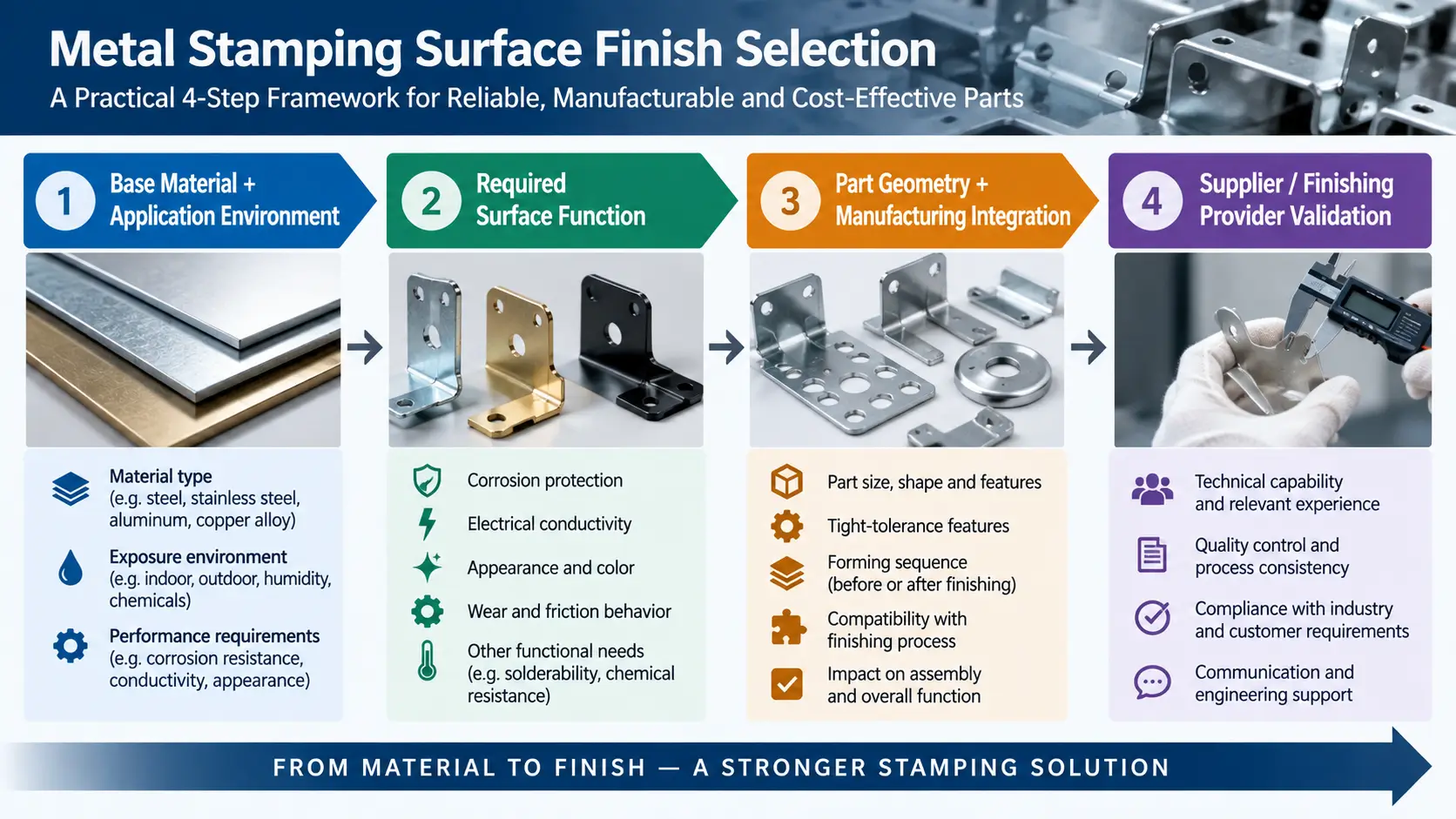
Surface Finish and Plating Considerations
Metal stamping surface finish requirements for stamped electrical contacts and connector terminals may be specified for corrosion protection, oxidation behavior, mating-interface requirements, appearance, or downstream assembly.
Depending on the application and customer requirements, electroplated finishes such as tin, nickel, or other coatings may be considered. Finish selection is influenced by the base alloy, environmental service conditions, mating interface requirements, and customer drawings.
Electroplating, powder coating, heat treatment, painting, and other secondary operations are coordinated through partner facilities where required.
Springback and Elastic Recovery in Formed Contact Features
After bending or forming, conductive metals can exhibit springback in metal stamping, causing the final geometry to differ from the shape under tooling load.
The degree of springback depends on the alloy, temper, thickness, bend radius, and forming sequence. Where springback affects a critical dimension, tooling compensation may involve adjusted forming geometry, staged forming, or other tooling changes based on actual material response during development.
Dimensional Tolerances and Inspection
Inspection requirements should focus on drawing dimensions and features that affect part geometry, mating, retention, and assembly fit. The metal stamping tolerances and metal stamping quality inspection guides provide broader context for dimensional requirements and verification.
Confirmed dimensional inspection tools include:
- Vernier calipers
- Micrometers
- Height gauges
First-piece dimensional inspection can be performed against the approved drawing and specified requirements. Independent testing can be coordinated through external laboratories or inspection resources when specified by the customer.
What OEM Buyers Should Include in a Contact or Terminal RFQ
A clear RFQ package helps the stamping supplier review material, tooling, manufacturability, inspection, and production requirements before quotation. Useful information includes:
- Current 2D Engineering Drawing: Include complete dimensions, tolerances, and drawing notes.
- 3D CAD Data: Where applicable, to clarify complex formed geometries.
- Material Grade and Specification: Explicit alloy identification.
- Material Temper or Condition: Where applicable to spring and forming behavior.
- Material Thickness: Drawing-specified thickness or material specification.
- Surface Finish / Plating Requirements: Coating specifications and environmental notes.
- Functional Interface Areas: Clear identification of mating, retention, or contact zones.
- Burr-Direction Requirements: Specified where edge orientation impacts assembly.
- Expected Annual Volume and Order Quantities: To support tooling and production planning.
- Inspection and Documentation Notes: Including Mill Test Report (MTR) requirements.
- Current Drawing Revision: Identify the revision to be used for quotation and production review.
Frequently Asked Questions
1. What materials are commonly used for stamped electrical contacts and connector terminals?
Custom stamped electrical contacts and connector terminals are commonly manufactured from copper, brass, and phosphor bronze alloys, depending on the required balance of electrical conductivity, mechanical strength, formability, and elastic behavior.
2. What is the difference between an electrical contact and a connector terminal?
An electrical contact is primarily a conductive interface component designed to transmit current or signals between mating surfaces. A connector terminal provides this electrical connection while often incorporating mechanical features like retention lances or crimp barrels for housing integration.
3. Why is phosphor bronze often used for stamped contacts?
Phosphor bronze is commonly considered for stamped contact applications where conductivity, strength, formability, and elastic behavior must be balanced. The correct choice still depends on the drawing, temper, thickness, forming requirements, and intended function.
4. Can connector terminals be made with progressive dies?
Yes. Progressive die stamping can be suitable for medium- to high-volume connector terminals and electrical contacts when the geometry, material, tolerances, and production volume justify a progressive tooling approach.
5. Why does burr direction matter on mating and retention features?
Burr direction determines whether the blanking breakout burr faces toward or away from mating interfaces and housing locking surfaces. An unfavorable burr orientation may contribute to mechanical binding, insertion interference, or seating problems, depending on the geometry and mating condition.
6. How does material temper affect stamped electrical contacts?
Material temper affects formability, springback, elastic response, and cracking risk. Softer conditions may tolerate more severe forming, while harder conditions may require different bend radii or forming strategies.
7. How are stamped contacts and connector terminals inspected?
Inspection is performed against the approved engineering drawing and specified requirements. Depending on the feature, dimensional inspection may use vernier calipers, micrometers, and height gauges. First-piece dimensional inspection can be performed before production proceeds under the agreed requirements.
8. What information should be included in a custom terminal RFQ?
A useful RFQ package normally includes the 2D engineering drawing, applicable CAD data, material grade, temper or condition where relevant, thickness, finish requirements, critical contact or retention areas, quantities, inspection requirements, documentation requirements, and the current drawing revision.
Send Your Contact or Terminal Drawing for Review
If you are sourcing custom stamped electrical contacts or connector terminals for an OEM electrical, electronic, appliance, or industrial application, review our custom metal stamping capabilities and send your 2D engineering drawings, CAD data, material requirements, quantity, and project specifications for manufacturing review and quotation.