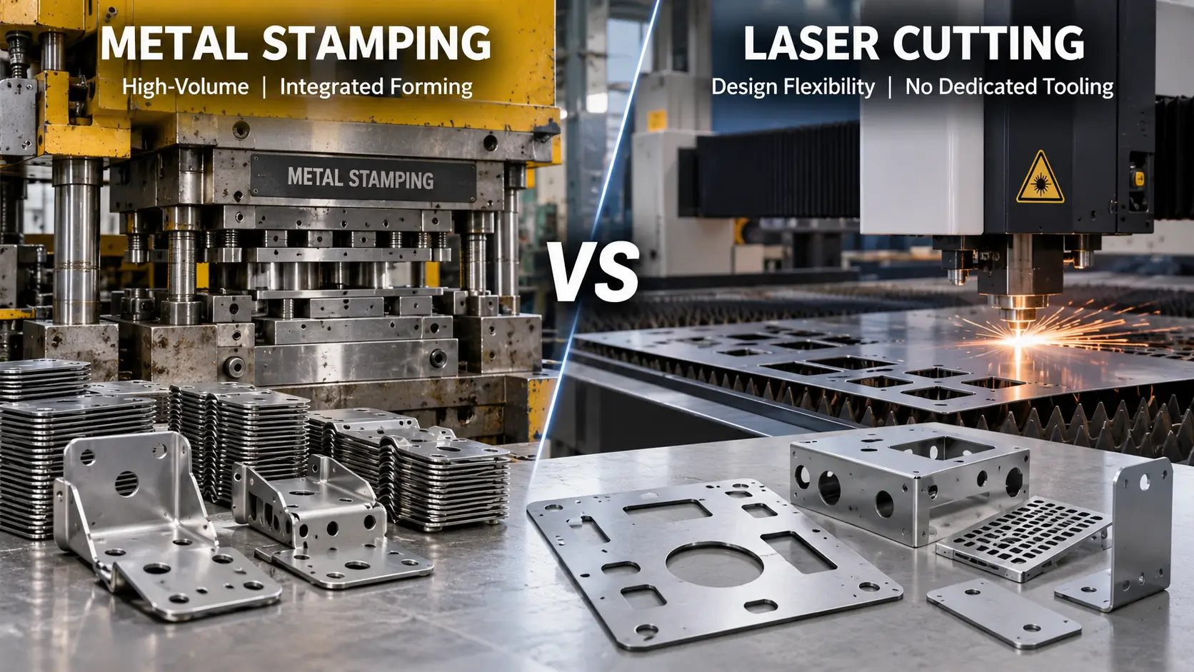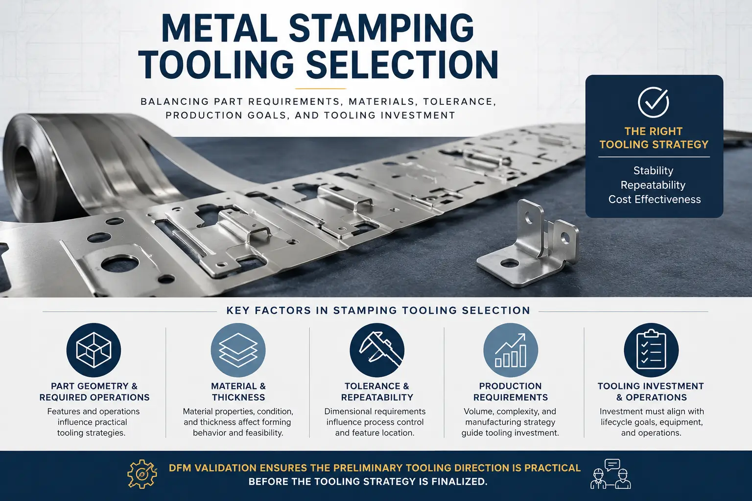
Evaluating a progressive die vs compound die architecture is a fundamental Design for Manufacturability (DFM) decision for custom sheet metal components. For OEM mechanical engineers, tooling designers, and sourcing managers, this choice directly influences non-recurring engineering (NRE) investment, unit piece cost, press machinery requirements, and part precision.
The decision is rarely as simple as comparing production volume or choosing between high and low tooling costs. Instead, the primary engineering boundary centers on how operations are distributed within the tool architecture: whether a component is formed sequentially across multiple stations on a continuous carrier strip, or produced through simultaneous cutting operations within a single station during a single press stroke. Aligning the physical requirements of the part with the correct die architecture requires evaluating operation types, dimensional relationships, part geometry, stripping mechanisms, and lifecycle economics.
Progressive Die vs Compound Die: Key Engineering Differences
| Factor | Progressive Die | Compound Die |
|---|---|---|
| Tool Architecture | Multiple stations arranged in sequence | Single station performing simultaneous cutting |
| Material Movement | Continuous strip with carrier web | Individual blanks or strip stock processed in one stroke |
| Main Operations | Piercing, bending, forming, drawing, coining | Blanking and piercing operations |
| Best Application | Complex 3D stamped parts | Flat precision components |
| Main Limitation | Carrier stability and station alignment | Limited forming capability |
Multi-Station vs Single-Station Tool Architecture
The primary structural difference between these two tooling styles lies in station layout and workpiece progression.
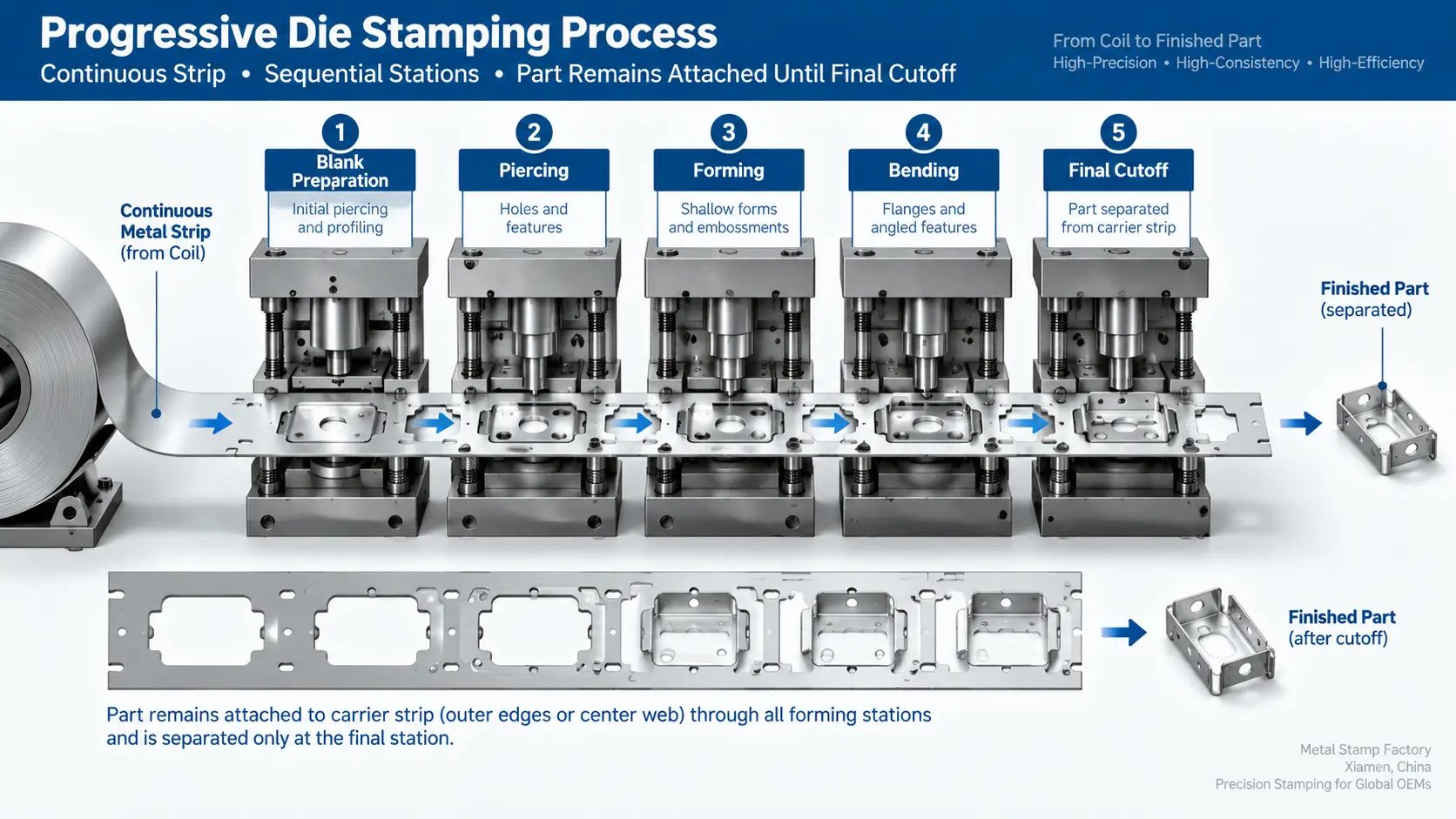
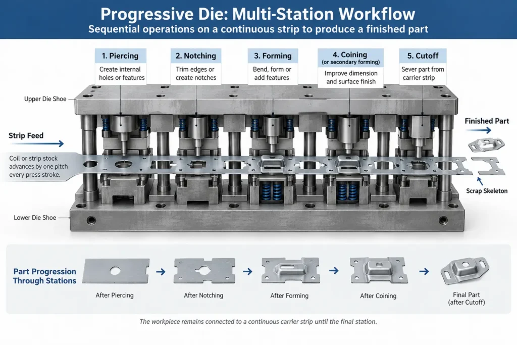
A progressive die consists of a series of sequential stations arranged linearly within a unified die shoe assembly. Strip or coil stock feeds into the tool at a fixed distance, known as the pitch, with every press stroke. As the stock advances, different cutting, punching, forming, or bending operations occur at consecutive locations. The workpiece remains attached to a continuous material web or carrier strip until the final station, where it is cut off or severed from the scrap skeleton.
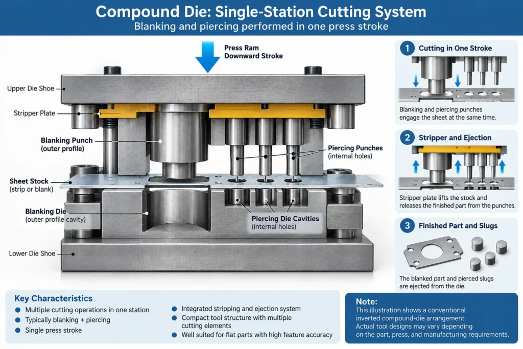
A compound die operates entirely within a single station. All cutting features required to define the part—such as punching internal openings and cutting the outer perimeter—engage the sheet metal simultaneously during one stroke of the press ram. Once the ram completes its downward cycle and retracts, the finished blank is severed from the stock and ejected from the tool without traveling to subsequent stations.
Sequential Operations vs Simultaneous Cutting Operations
Progressive tooling relies on sequential execution. By distributing complex forming steps across multiple stations, a progressive die can perform initial piercing, secondary notch trimming, multi-stage bending, drawing or forming operations where strip-carrier stability and material flow remain feasible, and coining on the same component as it travels through the tool. This multi-station approach allows material displacement or draw features to occur in stages without overstressing adjacent areas of the part.
Compound tooling relies on simultaneous execution. Because all cutting punches and die cavities engage the sheet metal during the same press stroke, the material undergoes shearing at all designated locations at once. This simultaneous action is well suited for cutting flat profiles, but it concentrates all cutting forces into a single tool footprint, requiring careful management of tool pressure, punch clearances, and ejection timing.
Part Geometry and Operation Requirements
Part geometry plays a key role in determining tooling suitability. Components requiring three-dimensional features—such as upward or downward flanges, drawn cups, louvered vents, or coined bosses—frequently require progressive tooling. These non-cutting operations need vertical clearance, specialized form blocks, or side-action cams that cannot easily be packaged into a single station alongside perimeter blanking dies.
Relatively flat components requiring high dimensional relationship control between internal features and outer perimeters are well suited for compound tooling. Examples include washers, shims, electrical motor laminations, flat brackets, and precision gears. Because the internal holes and external profile are sheared during the same stroke engagement, the geometric relationship between these features is established immediately in the tool.
Tooling Investment and Production Economics
Evaluating non-recurring engineering (NRE) costs between progressive and compound tooling involves analyzing station count, die size, and tool complexity rather than applying fixed pricing rules.
Progressive dies usually require larger die shoes, multiple punch and die sets, alignment pilots, and complex strip-lifting mechanisms. This multi-station construction can increase tooling investment and development effort depending on station count, forming complexity, die size, and precision requirements. However, because progressive dies run automatically from continuous coils with integrated strip feeding, they can achieve high production throughput with minimal manual part handling.
Compound dies integrate their cutting elements within a single tool set, which often results in a smaller physical die footprint for flat parts. However, because a compound die produces a loose blank inside the single station during every stroke, production throughput depends on reliable part stripping, slug clearance, and automated or mechanical ejection systems to maintain press stability.
How Progressive and Compound Dies Work
How a Progressive Die Moves Parts Through Multiple Stations
Progressive die stamping begins by feeding continuous coil stock into the press using an automated feeder. The feeder advances the metal strip into the die by a precise pitch distance with each press stroke.
Initial Stations: Piercing punches cut location pilot holes into the strip along with relief notches that define the outline of the part while leaving a connecting tab attached to the carrier web.
Intermediate Stations: Pilot pins mounted in the upper die lower into the pre-punched pilot holes to position the strip accurately. Bending, flanging, embossing, or shallow drawing punches engage the material. Because the part remains attached to the flexible carrier, material can flow locally without disrupting overall strip alignment.
Final Station: A cutoff or parting punch trims the attachment tab, releasing the finished component into a chute or container while the remaining carrier skeleton exits the rear of the press.
How a Compound Die Performs Multiple Cutting Operations in One Stroke
In a conventional inverted compound-die arrangement, the tooling performs simultaneous internal and external cutting through a specialized layout:
Tool Construction: The blanking punch for the outer profile is typically mounted on the upper die shoe facing downward, while the blanking die cavity is mounted on the lower die shoe facing upward. Inside the upper blanking punch, internal piercing die cavities are machined. Conversely, internal piercing punches are mounted inside the lower blanking die cavity pointing upward.
Stroke Engagement: As the press ram descends, the sheet metal stock is clamped firmly between spring-loaded stripper plates. Continuing downward, the upper blanking punch shears the outer perimeter against the lower die cavity. At the exact same time, the lower piercing punches shear the internal holes against the upper internal cavities.
Ejection Cycle: Depending on tool and press design, as the ram ascends, spring or hydraulic pressure forces the internal pierced slugs down through the lower punches, while an internal knockout system pushes the blanked part out of the upper die cavity so it can be cleared from the press bed.
Compound Die vs Combination Die: Important Terminology
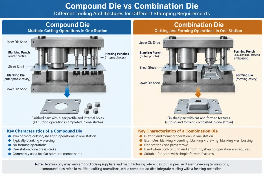
In die design and manufacturing engineering, terms are occasionally combined or used interchangeably by commercial suppliers, but a clear technical distinction exists:
Compound Die: Performs two or more cutting/shearing operations (such as simultaneous blanking and piercing) at a single station during a single press stroke.
Combination Die: Combines a cutting operation (such as blanking or piercing) with a non-cutting forming operation (such as bending, shallow drawing, or embossing) at a single station during a single press stroke.
When multiple cutting operations such as blanking and piercing are performed at one station in one stroke, compound die is the appropriate technical designation. Understanding this terminology helps engineers communicate tooling requirements clearly. If a flat component requires only sheared edges and pierced holes, a compound die represents the appropriate technical classification. If the component requires a blanking step combined with an immediate shallow draw or form in the same station, the tool operates as a combination die.
Part Geometry and Manufacturing Capability
Flat Blanked and Pierced Parts
For flat sheet metal components, compound tooling offers an effective manufacturing approach. When producing flat washers, shim stock, electrical laminations, or flat linkage arms, maintaining profile flatness and edge squareness is critical.
Holding the stock during simultaneous cutting can be advantageous for some flat-part applications, but final flatness still depends on material condition, cutting clearance, stripping pressure, residual stress, part geometry, and tool condition.
| Feature Requirement | Progressive Die | Compound Die |
|---|---|---|
| Flat Parts | Suitable | Highly suitable |
| Internal Hole Accuracy | Good with precision pilots | Excellent for same-stroke cutting |
| Bending Operations | Suitable | Limited |
| Deep Drawing | Possible with design considerations | Generally unsuitable |
| Multi-step Forming | Strong capability | Limited |
Parts Requiring Bending, Forming, or Multiple Operations
When a part geometry incorporates vertical legs, drawn cups, offset steps, or folded tabs, progressive tooling provides significant processing advantages.
Forming sheet metal requires space for material displacement, die radii, and springback control. Attempting to combine deep bends or complex forms into a single cutting station creates severe packaging interference and limits tool strength. In a progressive die, these operations are separated into logical steps:
Primary piercing and notch cutting establish the flat blank outline while attached to the carrier.
Pre-bending or relief embossing relaxes material stress.
Final flanging or wiping punches form vertical features over dedicated lower die blocks.
Final sizing or coining sets critical bend angles before part detachment.
Hole-to-Edge and Feature Relationship Considerations
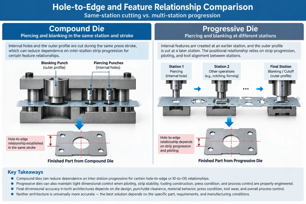
Controlling critical dimensions—such as hole-to-hole center distances, hole-to-edge margins, or inner-diameter to outer-diameter (ID-to-OD) concentricity—is a core requirement in precision stamping.
In a compound die, the internal piercing punches and outer blanking punch are retained within the same tool block assembly. Because these cutting elements engage the sheet metal during a single stroke, the geometric relationship between the internal holes and the outer edge is established simultaneously. This minimizes reliance on strip progression or pilot pin alignment for those specific feature relationships.
In a progressive die, internal holes are pierced at an early station, and the outer profile is trimmed or cut off at later stations. Positioning accuracy between these features depends on precise pilot pin engagement, feeder pitch accuracy, and carrier strip stability. While high-precision progressive dies maintain tight tolerances through ground pilots and rigid guide posts, the multi-station progression introduces a chain of station-to-station positioning variables that tooling designers must account for during strip development.
Strip Layout, Material Use, and Part Handling
Progressive Strip and Carrier Requirements
Progressive die design depends heavily on the carrier web. Because the workpiece must travel through consecutive stations without losing alignment, the strip layout must include dedicated material along the edges or center of the stock to act as a transport rail.
Carrier Types: Common configurations include side-rail carriers, center-web carriers, or stretch-tab bridges connecting adjacent parts.
Material Impact: The width and gauge of the carrier web add to overall coil width, creating skeleton scrap that cannot be incorporated into the final part geometry.
Strip Balance: The carrier web must maintain sufficient rigidity to withstand feed acceleration, lifting, and pilot engagement without twisting or buckling.
Compound Die Blank Layout, Part Ejection, and Slug Removal
In a conventional inverted compound-die arrangement, the tool operates without a continuous multi-station carrier rail, but introduces unique material handling and ejection considerations within the single station:
Strip Nesting: Raw strip or sheet stock is fed into the tool against stock stops or edge guides. The outer profile is blanked directly out of the strip, leaving only a perimeter scrap skeleton.
Slug Evacuation: Pierced internal slugs are forced downward through relief holes in the lower piercing punches or die plate, falling through the press bed.
Part Removal: Depending on tool and press design, the blanked workpiece remains pressed inside the upper die cavity after cutting. Near the top of the stroke, a mechanical knockout rod strikes a positive stop on the press frame, driving a knockout plate downward to eject the part from the upper tool. The part must then be cleared via gravity drop, an air blast, a mechanical shuttle, or a robotic picker before the next stroke.
Why Material Utilization Depends on the Specific Layout
| Factor | Progressive Die | Compound Die |
|---|---|---|
| Material Format | Continuous coil strip | Sheet or strip stock |
| Scrap Source | Carrier rails and skeleton scrap | Perimeter scrap and internal slugs |
| Optimization Method | Strip layout and carrier design | Nesting and blank arrangement |
| Main Challenge | Carrier material consumption | Nesting efficiency |
It is inaccurate to assume that compound dies always deliver superior material utilization or that progressive dies inherently produce excessive scrap. Material yield is a layout problem determined by part geometry and strip nesting efficiency.
In a compound die, while there is no carrier web, material efficiency depends on blank spacing, edge margin allowances, and whether the part shape permits tight nesting or interlocking patterns across the strip width.
In a progressive die, an experienced strip designer can often interlock irregular shapes, use dual-runner carriers, or share cutlines between adjacent parts to achieve high material yield. Material utilization must be evaluated by calculating gross-to-net material weight for a proposed strip layout rather than assuming an outcome based on die type.
Tooling Design, Press Requirements, and Maintenance
Progressive Die Station Count and Tool Complexity
The complexity of a progressive die scales directly with station count and forming steps. A complex progressive tool may contain numerous stations housed within a long sub-plate assembly.
Components: Incorporates guide posts, spring or hydraulic strip lifters, tapered pilot pins, side-cam slide mechanisms, and segmented die inserts.
Design Considerations: Tool designers must ensure that the strip can be lifted cleanly above lower die forms during advancement without distorting the carrier.
Compound Die Construction, Stripping, and Knockout Requirements
Although a compound die occupies a single station, its internal construction is dense and compact. Concentrating cutting and stripping functions into one footprint introduces specific tooling requirements:
Tooling Packaging: Upper and lower die shoes must house nested cutting elements, spring-loaded stripper plates, internal piercing punches, and positive knockout pins in a tightly constrained space.
Stripping Force: Spring, nitrogen, or other engineered stripping systems may be used to provide the required stripping force within the die assembly to ensure the upper stripper pad retracts cleanly from the stock after cutting.
Component Strength: Punch walls and die margins must maintain adequate steel cross-sections to withstand repeated shearing loads without cracking or deflecting.
Press Capacity, Tool Maintenance, and Production Stability
Press selection and long-term maintenance strategies differ based on die architecture:
Force Distribution: Progressive dies distribute active tooling features across a longer die footprint, while compound dies concentrate multiple cutting operations within one station. Press evaluation must consider the resulting load distribution, total required force, off-center loading, die footprint, press rigidity, and the specific operation sequence.
Ejection Synchronization: Compound dies require precise press stroke timing to actuate mechanical knockouts at the top of the stroke, ensuring the ejected blank clears the die face before the next stroke begins.
Maintenance and Sharpening: Sharpening a progressive die involves removing and grinding specific punch or die inserts at individual worn stations. Sharpening a compound die requires surface-grinding opposing upper and lower cutting faces simultaneously, requiring careful adjustment and shimming of stripper pads, knockouts, and punch penetration depths to maintain tool balance.
Production Economics and Lifecycle TCO
Tooling NRE and Initial Investment
Non-recurring engineering (NRE) costs represent the capital expenditure required to design, machine, assemble, and try out a new stamping die set.
Factors such as higher station count, longer die sets, precision piloting, and integrated forming mechanisms can increase progressive tooling NRE. Conversely, while a compound die occupies a single station, the need for high-precision cutting elements, intricate stripping, positive knockout systems, and tight tool packaging can also lead to significant tooling investment. Total NRE must be evaluated based on the specific tool architecture and component requirements rather than assumed defaults.
Production Rate and Unit-Cost Considerations
Operating speed and labor requirements directly influence the final unit part cost over a production run:
Automated Progressive Stamping: Progressive dies run smoothly on coil-fed presses equipped with automated feeders. Because parts remain anchored to the carrier strip through all operations, the press can run continuously at high cycle rates with minimal operator intervention.
Compound Stamping: Compound dies can also run on coil-fed automated lines when equipped with reliable air-blast, vacuum, or shuttle ejection systems. However, if part geometry or thickness prevents automated ejection, manual or semi-automated blank feeding and removal may be necessary, which reduces cycle speeds and increases labor cost per piece.
Why Production Volume Alone Does Not Determine Die Type
A common misconception in tooling procurement is that production volume alone dictates die selection—for example, assuming low volumes require compound dies and high volumes require progressive dies.
In practice, production volume is only one variable in the economic equation. A flat, high-volume precision component may still be well suited to compound tooling because of strict concentricity requirements and efficient knockout ejection. Conversely, a complex bracket required in modest annual volumes may justify a progressive die because manual multi-stage forming across separate secondary presses would create unsustainable labor and handling costs.
A lifecycle TCO comparison should account for initial tooling NRE, unit production cost, material consumption, setup, maintenance, labor, press utilization, and other operating overhead across the expected program life.
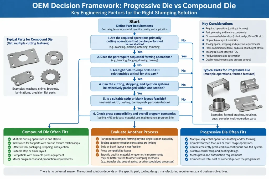
OEM Decision Framework: Progressive Die vs Compound Die
| OEM Requirement | Progressive Die | Compound Die |
|---|---|---|
| Part Shape | 3D formed components | Flat stamped components |
| Operation Type | Multiple sequential operations | Simultaneous cutting |
| Accuracy Priority | Multi-feature formed parts | Hole-to-edge relationships |
| Production Method | Coil-fed automation | Single-stroke production |
| Tool Selection Driver | Geometry complexity | Precision cutting requirement |
When Progressive Die Is Often the Better Fit
Progressive die tooling is generally indicated when an evaluation of the part and manufacturing process reveals the following requirements:
The component requires three-dimensional forming, such as bending, flanging, drawing, embossing, or coining.
The part can maintain stable attachment to a carrier strip throughout all forming stages without distorting.
The required operations can be integrated efficiently into continuous coil-fed multi-station production.
Operations are too numerous or complex to package safely inside a single tool station.
Complex forming operations can be divided into controlled sequential stages rather than being packaged into a single station.
When Compound Die Is Often the Better Fit
Compound die tooling is generally indicated when the part requirements align with these process characteristics:
The component is flat or flat-profiled, requiring only shearing operations such as blanking, piercing, or slotting.
Tight dimensional relationships between internal pierced features and the outer blanked perimeter (such as hole-to-edge margins or ID-to-OD concentricity) are critical.
Multiple cutting features can be integrated effectively within one station without creating impractical tooling-space, strength, stripping, or ejection constraints.
The part shape permits efficient strip nesting without requiring a dedicated multi-station carrier web.
Reliable part ejection (via knockout mechanisms, air assist, or mechanical shuttles) can be integrated into the press stroke.
When Another Stamping Process Should Be Evaluated
Certain component requirements fall outside the capabilities of both progressive and compound dies, indicating that alternative stamping configurations should be considered:
Large or Heavy Workpieces: Very large, thick structural parts that exceed continuous carrier strip strength or single-station bed dimensions may be better suited for transfer die stamping or multi-press tandem lines.
Deep Drawn Shells: Drawn components where cup depth relative to diameter requires extensive material draw ratios and inter-stage washing or annealing may require transfer processing.
Simple Blanks: Extremely simple flat shapes with minimal program volumes may be produced more economically using laser cutting, turret punching, or simple single-operation blanking tools to avoid specialized NRE investment.
Frequently Asked Questions
What is the primary difference between a progressive die and a compound die? A progressive die distributes cutting and forming operations across multiple sequential stations, advancing the part through the tool on a continuous carrier strip. A compound die performs multiple cutting operations—such as blanking the outer profile and piercing internal holes—simultaneously at a single station during one press stroke.
Is a compound die always less expensive to build than a progressive die? No. A compound die may require fewer stations, but part geometry, cutting-feature complexity, precision requirements, stripping and ejection systems, tool size, and press requirements ultimately determine total tooling NRE.
Which die architecture provides better hole-to-edge location accuracy? Neither architecture is universally more accurate. For certain flat parts, performing piercing and outer-profile blanking in the same station and stroke can reduce dependence on inter-station progression when controlling hole-to-edge or ID-to-OD relationships. Progressive dies can also maintain tight dimensional control when piloting, strip stability, tooling construction, press condition, and process control are properly engineered.
What is the difference between a compound die and a combination die? A compound die performs only cutting operations (such as blanking and piercing) simultaneously in one station. A combination die combines a cutting operation with a non-cutting forming or shaping operation (such as blanking combined with bending or shallow drawing) within a single station during a single stroke.
Can a compound die handle parts that require bending or forming? Pure compound dies are designed for cutting operations. Incorporating vertical bends, deep flanges, or three-dimensional forms alongside perimeter blanking requires specialized tool packaging, often moving the process into a combination die or distributing the forming steps across a multi-station progressive die to preserve tool strength and allow proper part ejection.
Conclusion
Selecting between a progressive die and a compound die requires an engineering evaluation of part geometry, dimensional tolerance requirements, forming sequences, material handling, and total program economics. Rather than relying on simplified rules regarding production volume or tooling cost, OEM engineering and procurement teams achieve optimal outcomes by matching the physical requirements of the component to the operational mechanics of the die architecture.
For detailed DFM reviews, strip layout analysis, and tooling recommendations for custom sheet metal stamping programs, contact the engineering team at Metal Stamp Factory in Xiamen, China.