Founder of Metal Stamp Factory with more than 25 years of hands-on experience in tooling development, metal stamping, and OEM production.
Introduction
In precision sheet metal manufacturing, maintaining consistent part quality requires careful control over tooling assets. Stamping die wear is the gradual deterioration of cutting edges, forming radii, and other working surfaces that can develop over repeated production cycles. As punches and die components interact with sheet material under load, friction, impact, and repeated contact may gradually change the tool’s working condition and geometry.
Understanding the progression of die wear in metal stamping is important for maintaining stable production and avoiding unnecessary tooling damage. Changes in dimensions, cut-edge condition, surface appearance, or press behavior may accompany tooling deterioration, but these symptoms can also have other causes. Pressroom teams therefore need to distinguish gradual wear from sudden mechanical failure, such as localized chipping or breakage.
To manage tooling condition effectively without performing premature maintenance or risking catastrophic tool failure, pressroom personnel rely on a core diagnostic principle:
Changes in burrs, dimensions, surface condition, or press behavior are warning signs—not proof of one specific wear mechanism.
Evaluating physical symptoms systematically allows engineers to determine whether a part quality shift stems from natural edge breakdown, improper alignment, unmitigated friction, or material contamination before selecting corrective action. Tooling deterioration can contribute to several common metal stamping defects, but the visible part symptom should still be traced back to the actual tooling and process condition.
What Is Stamping Die Wear?
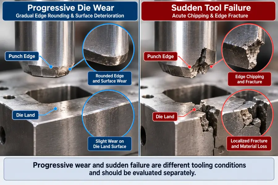
Progressive Wear vs. Sudden Tool Failure
Stamping die wear refers to gradual material removal, surface change, or geometric deterioration on active tooling surfaces. Wear can accumulate over repeated cycles as sheet material is cut, formed, or slides against the tool. Progressive wear is usually managed through condition-based stamping die maintenance, lubrication review, cleaning, edge restoration, and other application-specific maintenance actions.
In contrast, sudden tool failure involves acute structural damage such as major edge chipping, fracture, or permanent deformation. Unlike gradual wear, this type of failure can occur unexpectedly when unusual loading, misfeeds, alignment problems, material variation, or other abnormal production conditions affect the die. Diagnostic review should separate progressive deterioration from sudden failure before corrective action is selected.
Where Wear Commonly Develops
Tooling wear does not occur uniformly across a die assembly. Specific areas experience concentrated friction and impact loads:
- Punch Edges: The perimeter cutting edges of piercing and blanking punches absorb direct impact shock and high shear stress on every stroke, making them highly susceptible to edge breakdown.
- Die Edges / Die Land: Lower die openings and matrix lands experience continuous sliding contact as sheared material passes through, leading to lateral wall erosion and top-edge breakdown.
- Forming Radii: Radii on draw beads, wipe dies, and flanging stations endure intense friction and contact pressure as sheet metal slides over the tool contour under tension.
- Contact Surfaces: Stripper plates, pressure pads, and stock support faces experience high cyclic clamping forces, which can lead to localized surface burnishing or minor thickness loss over time.
- Guidance / Alignment-Related Areas: Guide pins, bushings, heel blocks, and wear plates maintain spatial relationship between the upper and lower die sets. Wear in these areas leads to spatial play, accelerating uneven wear on primary cutting components.
Common Types of Stamping Die Wear
Abrasive Wear
Abrasive wear is one common wear mechanism in sheet metal processing. AHSS Guidelines provides additional technical background on tooling and die wear. It can develop when harder constituents in the workpiece, surface oxides, scale, or trapped particles repeatedly contact the tooling surface. Over time, this interaction may produce fine wear tracks or gradual material loss along cutting edges, die lands, and forming surfaces.
Adhesive Wear
Adhesive wear develops under severe sliding friction and intense local contact pressure, where microscopic surface asperities on the workpiece cold-weld to the tool steel face. Continued sliding shears these tiny micro-welds, causing minute fragments of material to transfer between surfaces or break away entirely. In severe forms, prolonged adhesive transfer can develop into localized material pickup on tool radii. When adhesive transfer becomes a recurring surface problem, the detailed diagnosis of galling and material pickup should be treated separately from the broader die-wear review.
Edge Rounding
Edge rounding describes the progressive loss of a sharp cutting corner on punches and die matrices. Repeated cutting and impact can gradually change the edge profile into a small radius. As this develops, cutting behavior and part edge quality may change, making edge condition an important maintenance clue.
Micro-Chipping and Chipping
Micro-chipping occurs when small localized fragments of tool material break away along a cutting or forming edge instead of wearing gradually. It may be associated with repeated impact, side loading, localized stress concentration, material variation, or prior tooling damage. A micro-chipped area can become a starting point for further damage, but the actual cause should be confirmed from the tooling and production conditions.
Plastic Deformation
Plastic deformation occurs when localized contact stresses exceed the yield strength of the tool material at operating temperature. Rather than wearing away via friction, the tool steel physically deforms, mushrooming punch tips or flattening small forming radii. This mechanism can become more likely under high local loads, elevated contact temperatures, or tooling conditions that reduce the material’s resistance to deformation.
Surface Fatigue or Localized Surface Breakdown
Under repeated, cyclic loading, the subsurface layer of a tool steel matrix endures alternating stress fields. Over prolonged production, repeated cyclic stresses can contribute to subsurface fatigue damage. In some cases, localized cracking or small pits may develop at the working surface.
What Causes Stamping Dies to Wear Faster?
Material Strength and Surface Condition
The physical properties and surface condition of the incoming stock can influence wear severity:
- Material Strength: Higher-strength materials can increase cutting and forming loads and may accelerate wear under some tooling conditions.
- Work-Hardening Characteristics: Materials that strengthen during deformation can increase resistance as forming progresses.
- Surface Oxides and Contamination: Scale, oxide, or abrasive contamination can increase surface interaction and contribute to wear.
Punch-to-Die Clearance and Cutting Conditions
Punch-to-die clearance can influence cutting forces, friction, and wear patterns. Clearance that is too tight for the specific application may increase cutting load and friction, while uneven clearance can contribute to non-uniform wear on punches and die edges.
Misalignment and Uneven Loading
Systematic alignment errors introduce localized stress concentrations across the die assembly:
- Press or Die Deflection: Deflection under load can alter the intended relationship between upper and lower tooling.
- Guide Component Wear or Play: Changes in guidance components can allow localized movement or uneven loading.
- Unbalanced Loading: Uneven loading across the die may contribute to localized edge deterioration or non-uniform wear.
Lubrication and Friction
Lubrication helps reduce friction and direct metal-to-metal interaction. If lubricant performance or coverage is not suitable for the local contact conditions, friction and heat may increase and contribute to accelerated wear. Lubrication should therefore be reviewed together with material, contact severity, and tool-surface condition.
Debris and Contamination
Foreign material inside the die can contribute to abrasive contact or localized damage. Loose slivers, coating debris, scale, dirt, or trapped scrap may be dragged across active surfaces and accelerate deterioration. Material cleanliness and the condition of relevant contact areas should be reviewed when wear becomes localized or changes unexpectedly.
Repeated Overload or Impact
Repeated overload, unusual impact, misfeeds, or other abnormal loading events can accelerate edge damage or contribute to sudden chipping. When deterioration appears abruptly rather than gradually, the production history and recent operating changes should be reviewed before assuming normal wear.
Tool Material and Heat-Treatment Suitability
General industry practice involves selecting tool steels, carbides, or specialized surface treatments matched to the specific application. Tool-material or heat-treatment choices that are poorly matched to the application can increase the risk of accelerated edge rounding, chipping, or plastic deformation.
Warning Signs of Stamping Die Wear
Increasing Burrs or Changing Cut-Edge Quality
An increase in burrs or a change in cut-edge appearance can be a warning sign that cutting-edge condition has changed. Worn or rounded edges are one possible contributor, but burr growth can also be influenced by clearance, alignment, material condition, or other process variables. Detailed burr formation and troubleshooting remain a separate cut-edge topic.
Dimensional Drift
A gradual change in a critical dimension can be a warning sign that tooling geometry, guidance, alignment, or working conditions have changed. Dimensional drift should be compared with the affected feature, recent production history, and the relevant tool surfaces before wear is assigned as the root cause.
Changes in Surface Marks
New or increasingly repeatable surface marks can indicate a change in tool-surface condition, contamination, lubrication, alignment, or material transfer. The mark pattern should be treated as a diagnostic clue rather than proof of one specific wear mechanism.
Increasing or Changing Press Load
A change in press load or stripping behavior may accompany changes in cutting edges, friction, alignment, material condition, or other production variables. Load changes should therefore be reviewed together with the tooling condition and recent setup history rather than used alone to diagnose die wear.
Abnormal Noise or Vibration
New noise, vibration, or impact characteristics can signal a change in tooling or process conditions. Possible contributors include loose components, misalignment, abnormal loading, debris, wear, or other mechanical changes. Production should be reviewed before assuming normal progressive wear.
Visible Edge Rounding or Chipping
Direct visual evidence of edge rounding, localized chipping, or other surface deterioration is a stronger tooling clue than part symptoms alone. Even so, the location and extent of the damage should be evaluated before deciding whether sharpening, repair, or replacement is appropriate.
Repeatable Defect Progression
A part-quality problem that becomes more consistent or severe over repeated production may be related to progressive tooling deterioration, but repeatability alone does not prove die wear. The part trend should be compared with tool condition, maintenance history, material changes, lubrication, alignment, and other relevant process factors.
Troubleshooting Suspected Stamping Die Wear
The table below summarizes useful diagnostic clues. These are starting points for review, not deterministic root-cause rules.
| Observation | Possible Tooling / Process Areas to Review | Why It Matters |
|---|---|---|
| Increasing burrs or changing cut-edge appearance | Cutting-edge condition, clearance, alignment, material condition | Worn edges are one possible contributor, but burr changes can have multiple causes. |
| Gradual dimensional drift | Tool geometry, guidance, alignment, forming or cutting surfaces | Dimensional change can accompany tooling deterioration or setup changes. |
| New or repeatable surface marks | Tool surface, contamination, lubrication, alignment, material pickup | Surface symptoms can point to contact-condition changes but do not identify one cause by themselves. |
| Changing press load or stripping behavior | Cutting condition, friction, alignment, material variation, tooling condition | A load shift can indicate a process change that warrants tooling review. |
| New noise or vibration | Loose or damaged components, misalignment, debris, abnormal loading | Mechanical changes should be investigated before assuming routine wear. |
| Visible edge rounding or localized chipping | Punch edge, die edge, forming radius, affected insert or component | Direct tooling damage helps narrow the maintenance decision. |
| Repeating or worsening part-quality trend | Tool condition, maintenance history, material, setup, lubrication | Trend data can help correlate part symptoms with tooling changes over time. |
Sharpening, Regrinding, Repair, or Replacement?
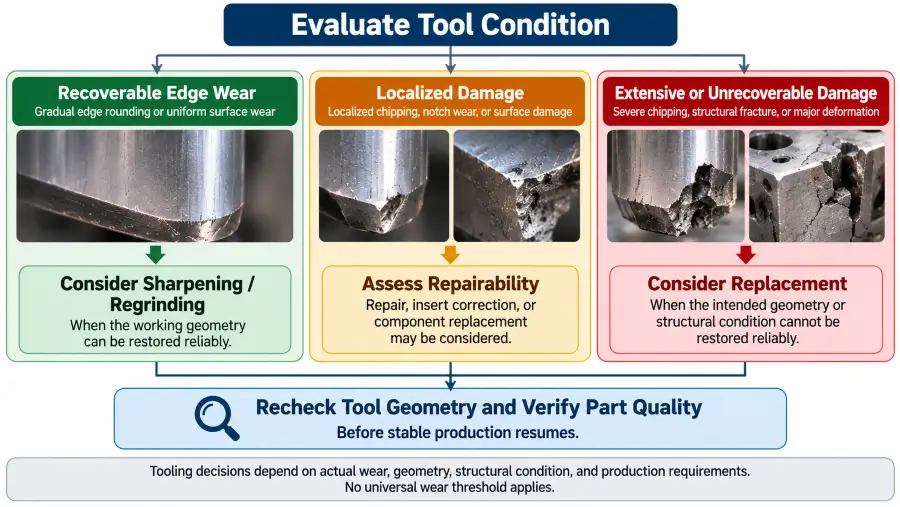
The correct maintenance response depends on the actual tooling condition. Edge restoration may be appropriate when the intended working geometry can be recovered reliably, while localized or structural damage may require a broader repair assessment or component replacement.
When Sharpening May Be Appropriate
Stamping die sharpening or die regrinding may be used to restore a worn cutting edge when the component remains structurally recoverable. Wilson Tool also discusses general punch maintenance and regrinding concepts. The goal is to remove only the material necessary to restore the intended working geometry without unnecessarily reducing remaining tool life. The exact method and amount of material removed depend on the tool design and wear condition.
When Repair May Be Needed
When tooling exhibits localized chipping, notch wear, or other damage that cannot be corrected through normal edge restoration, a more substantial repair may be required. General industry approaches can include localized correction, insert repair or replacement, geometry restoration, or other application-specific tooling work.
When Replacement Should Be Considered
Component replacement may be appropriate when damage exceeds practical or economic recovery limits. Factors to consider include:
- The remaining shear land or working stroke depth is fully depleted from repeated past sharpening cycles.
- Deep structural cracks extend through the main body of a punch or die insert.
- Repeated localized repairs have compromised the structural integrity or dimensional stability of the component.
- Replacing a standard modular punch or matrix insert is more cost-effective than extensive custom rebuild work.
Why Over-Grinding Can Create New Problems
While regrinding restores edge sharpness, removing excess tool steel in a single maintenance event can introduce secondary issues:
- Depleting Tool Geometry: Grinding beyond the required depth to clear a wear mark shortens the remaining service life of the tool unnecessarily.
- Thermal Damage: Aggressive or poorly controlled grinding can introduce excessive localized heat and may damage the tool surface or alter material properties.
- Punch/Die Relationship Shifts: Grinding punch faces without properly adjusting backing plates, stripper engagement depths, or shut height settings can alter component timing, misalign entry depths, or cause stock feeding interference.
General Stamping Die Maintenance Strategy
A structured stamping die maintenance strategy focuses on condition-based review and timely corrective action rather than waiting for severe damage to appear.
Clean and Review Contact Areas
Maintenance may include cleaning relevant tooling and contact areas so wear, damage, contamination, and surface condition can be reviewed more clearly.
Monitor Edge and Surface Condition
Reviewing active edges and contact surfaces over time can help identify changes before they develop into larger production problems. Where appropriate, observations such as edge rounding, chipping, surface deterioration, or localized pickup can be recorded and compared with part-quality trends.
Compare Part-Quality Trends
Part-quality trends can provide useful maintenance clues. Changes in burr condition, dimensions, surface appearance, or other critical features should be compared with the corresponding tooling condition before a sharpening or repair decision is made.
Record Maintenance History
Maintaining a tooling history can help track previous sharpening, repair, insert replacement, abnormal damage, and other maintenance events. Historical information can be useful when the same wear pattern or station-level problem recurs.
Recheck Tool Geometry After Maintenance
Following sharpening, repair, or component replacement, the relevant tooling geometry and relationships should be rechecked before stable production resumes. Depending on the die, this may include edge condition, punch and die relationship, alignment, working height, guidance, and other geometry affected by the maintenance work.
Review Lubrication and Alignment
Restoring an edge does not by itself address every contributor to accelerated wear. Lubrication, alignment, guidance condition, material changes, and other relevant production conditions should also be reviewed where abnormal wear recurs.
Avoid Fixed Maintenance Intervals
There is no universal stroke count or calendar interval that applies to every die. Maintenance timing should be based on the actual tooling and production conditions, including:
- Workpiece Material: Material strength, surface condition, and abrasiveness can influence wear rate.
- Lubrication: Changes in lubricant performance or coverage can affect friction and tool condition.
- Part-Quality Trends: Burr condition, dimensions, surface appearance, and other relevant features can provide maintenance clues.
- Tooling Design and Material: Different tooling materials, inserts, coatings, and geometries can behave differently in service.
- Production History: Previous wear patterns, repairs, and abnormal events can help determine what should be reviewed next.
Tooling Maintenance Responsibility for OEM Projects
When managing custom tooling development and high-volume OEM production runs, establishing clear commercial and technical guidelines for die maintenance is critical for long-term project success.
Metal Stamp Factory uses the following verified commercial and tooling-maintenance policies for OEM tooling projects:
- Tooling Production Initiation: Formal die production begins after the customer tooling fee is paid in full.
- Tooling Lead Times:
- Conventional single-operation dies normally require about 15–25 days, depending on the part drawing and tooling complexity.
- Progressive dies normally require about 35–40 days.
- Projects involving multiple tooling sets may require around 50 days, depending on the number and complexity of the dies required.
- Tooling Design: Tooling design is completed by Metal Stamp Factory.
- Tooling Storage: Tooling is stored free of charge for 3 years.
- Retention Policy: If no order is placed for a specific tooling set during a continuous 3-year period, the tooling is not retained afterward.
- In-Production Tooling Responsibility: During normal part production, required tooling maintenance, repair, or remake is handled by the factory, while any significant tooling event that may affect the production schedule is communicated to the customer.
Real Production Perspective
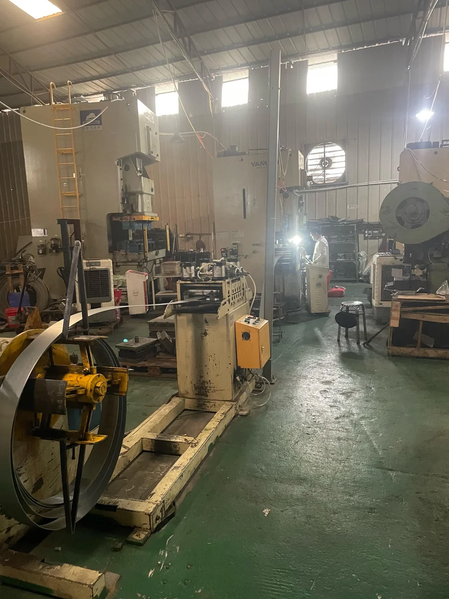
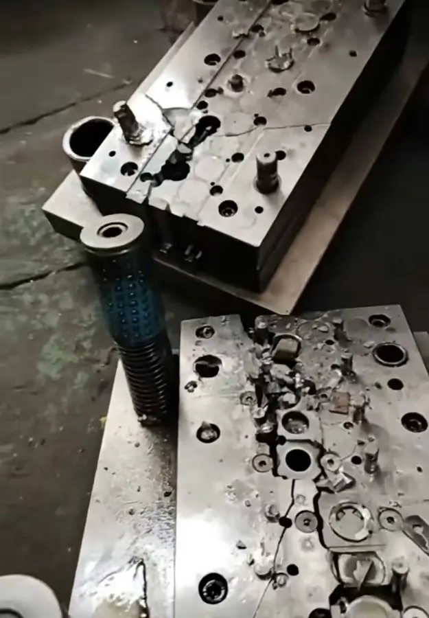
In one real production event at Metal Stamp Factory, a die suffered sudden, extensive damage during production. This type of event is uncommon, but it illustrates an important distinction in tooling management: not every tooling problem develops gradually through normal wear. Unexpected mechanical damage can occur even when preventive work and routine checks are in place.
The damaged die was first evaluated to determine whether the affected tooling could be repaired. When production tooling is damaged during normal production, the customer is not charged an additional tooling fee for the required repair or remake. If the damage is repairable, the factory handles the required tooling maintenance and repair. If the die cannot be restored reliably, Metal Stamp Factory manages the replacement tooling design and final assembly, while specialized die-component machining is coordinated through qualified external partner facilities as required. The customer is informed of the tooling-production time and any resulting effect on the production or delivery schedule.
When remaking a die is necessary, the tooling-production time must be communicated to the customer as early as possible so the revised manufacturing schedule and part-delivery plan can be coordinated. The practical priority is to restore stable production while keeping the customer informed of any schedule impact caused by the tooling event.
What OEM Buyers Should Ask About Die Wear and Maintenance
When evaluating a stamping supplier’s technical capability or investigating part quality variations during an active production contract, OEM procurement and quality teams should ask the following questions:
- Which punch, insert, edge, or forming area is showing wear?
- Purpose: Helps identify which station or tooling component should be reviewed first.
- What part-quality change first indicated the problem?
- Purpose: Helps compare the first observed part-quality change with the corresponding tooling condition without assuming a single cause.
- Is the wear gradual, localized, or associated with sudden damage?
- Purpose: Helps separate gradual deterioration from localized or sudden damage before selecting a maintenance response.
- Did the issue begin after a material, lubricant, setup, or tooling change?
- Purpose: Helps identify recent changes that may be relevant to the wear or failure pattern.
- What maintenance or corrective action was performed?
- Purpose: Clarifies what corrective work was performed and what tooling condition it was intended to address.
- Was the relevant tooling geometry rechecked after maintenance?
- Purpose: Confirms that the tooling geometry and relationships affected by maintenance were reviewed before production resumed.
- How was the corrective action verified before production resumed?
- Purpose: Confirms that the corrective action was checked on both the tooling and the produced parts through appropriate metal stamping quality inspection before stable production resumed.
Frequently Asked Questions
1. What causes stamping dies to wear prematurely?
Accelerated die wear can be influenced by material strength and surface condition, unfavorable clearance, misalignment, lubrication, contamination, repeated impact, and tooling-material suitability. The actual cause should be confirmed from the location and wear pattern rather than assumed from one symptom.
2. What are the early warning signs of stamping die wear?
Early warning signs may include changes in burr condition, dimensions, surface marks, press load, sound or vibration, and visible edge condition. These observations are diagnostic clues and should be compared with the corresponding tooling and recent process changes.
3. How do you know when a stamping punch or die needs sharpening?
Sharpening may be appropriate when edge deterioration is affecting part quality and the cutting component remains structurally recoverable. The decision should be based on the actual tool condition, part-quality trend, and geometry rather than a fixed stroke count or universal wear threshold.
4. How often should stamping dies be maintained?
There is no universal maintenance interval or fixed stroke schedule. Maintenance timing depends on workpiece material hardness, sheet thickness, lubricant effectiveness, tooling design, and observed part-quality trends. Tooling condition should be reviewed based on actual production conditions and part-quality trends rather than an arbitrary stroke count.
5. Can a worn or chipped stamping die be repaired?
Yes, depending on the severity and location of the damage. Minor edge wear may sometimes be corrected through regrinding when the tooling remains structurally and dimensionally recoverable. Deeper chipping, localized notch wear, or cracked areas may require localized repair, insert replacement, regrinding, or other application-specific tooling work to restore the intended working geometry.
6. When should a punch or die insert be replaced instead of reground?
A punch or die insert may need replacement when the component is no longer structurally or dimensionally recoverable, when damage is too extensive for reliable repair, or when replacement is more practical than continued corrective work.
About Metal Stamp Factory
Metal Stamp Factory was established in 2014 in Xiamen, China, focusing on custom metal stamping and precision hardware manufacturing. The founder of Metal Stamp Factory, Shengtong Chen, started learning mold making and metal stamping at the age of 17 and has accumulated more than 25 years of hands-on manufacturing experience in tooling development, metal stamping, and OEM production.
For tooling-related production issues, our approach is to review the affected tooling condition together with recent material, setup, lubrication, and part-quality changes before deciding on corrective action. During normal part production, required tooling maintenance or repair is handled by the factory, while any significant tooling event that may affect the production schedule is communicated to the customer.