Choosing the right tooling architecture for custom metal stamping is an essential Design for Manufacturability (DFM) decision. For OEM mechanical engineers, tooling designers, and procurement managers, the decision often centers on evaluating two multi-stage automated production methods: progressive die stamping and transfer die stamping.
The core distinction between these two systems is not determined by annual production volume, press speed, or initial tooling cost alone. Instead, the primary engineering boundary lies in how material and developing workpieces move through the press. Progressive dies advance material through consecutive stations while the component remains physically attached to a continuous metal strip or carrier. Transfer die systems separate the workpiece from the stock early in the process and move independent blanks between forming stations using mechanical or servo-driven transfer mechanisms.
Evaluating progressive die vs transfer die architectures requires a balanced review of part geometry, blank development, forming sequences, material properties, carrier-strip feasibility, press capabilities, and lifecycle economics. Neither process is universally superior. The optimal selection depends on aligning the mechanical requirements of the part with the operational strengths of the tooling architecture.
Progressive Die vs Transfer Die: Quick Comparison
Evaluating the technical differences between progressive and transfer tooling requires examining material movement, investment requirements, throughput, material efficiency, geometric limits, and press equipment.
| Factor | Progressive Die | Transfer Die |
|---|---|---|
| Material Movement | Part remains attached to carrier strip while moving through stations | Individual blanks are transferred between stations |
| Material Handling | Coil-fed production with controlled strip feed | Uses mechanical or servo transfer systems |
| Tool Structure | Multiple operations integrated into one die set | Separate die stations arranged along press line |
| Best Application | High-volume parts with stable geometry | Large, deep-drawn, or complex formed components |
| Main Limitation | Carrier stability limits severe forming operations | Higher automation and equipment complexity |
Manufacturing & Material Movement
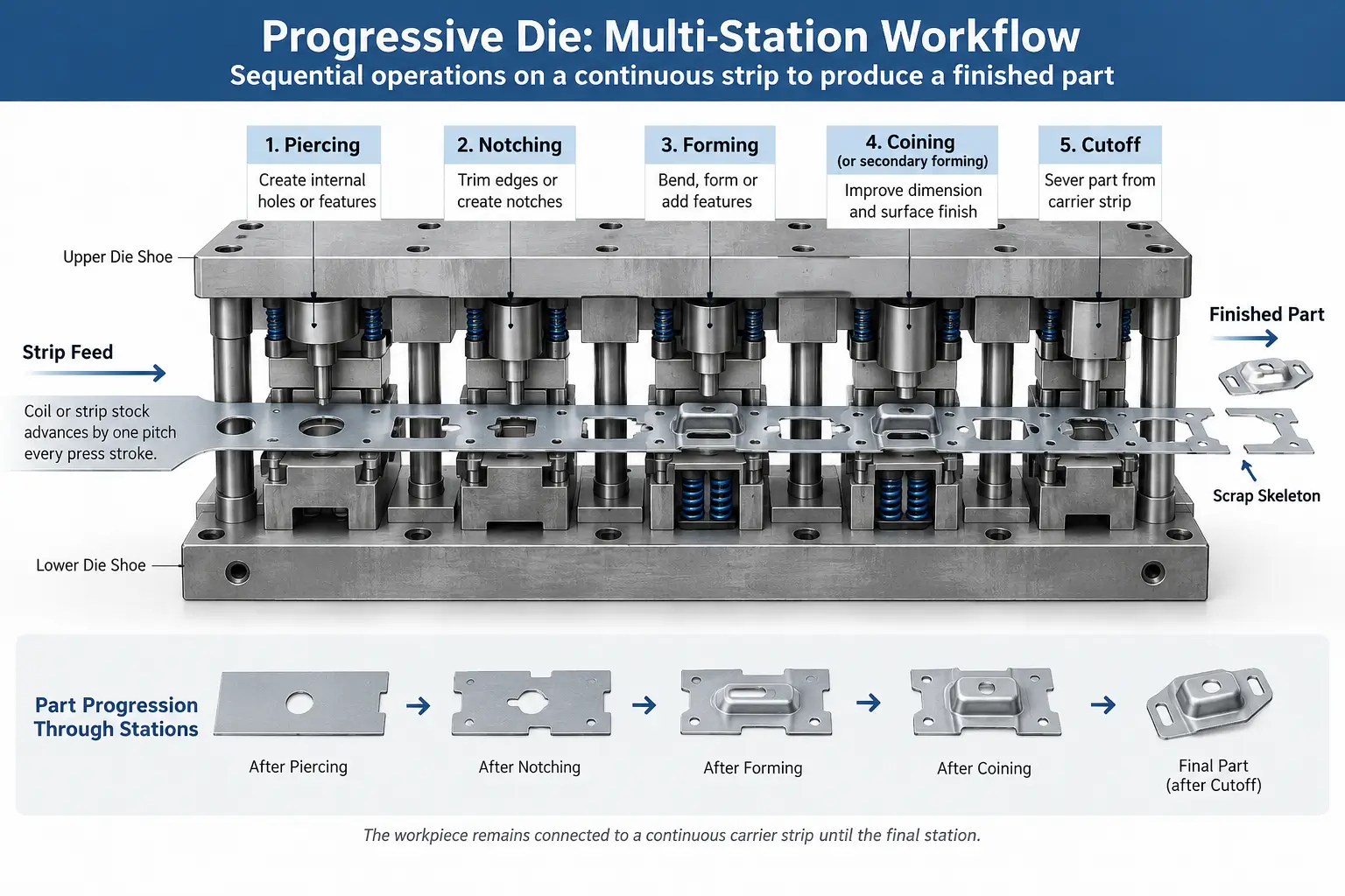
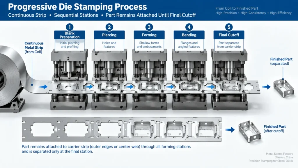
In progressive die stamping, raw coil stock feeds into the press continuously. As the press cycles, the material advances by a precise feed pitch. The developing part remains attached to the outer edges or center web of the coil stock—known as the carrier strip—as it travels from station to station. The finished component is separated from this carrier skeleton only at the final station.
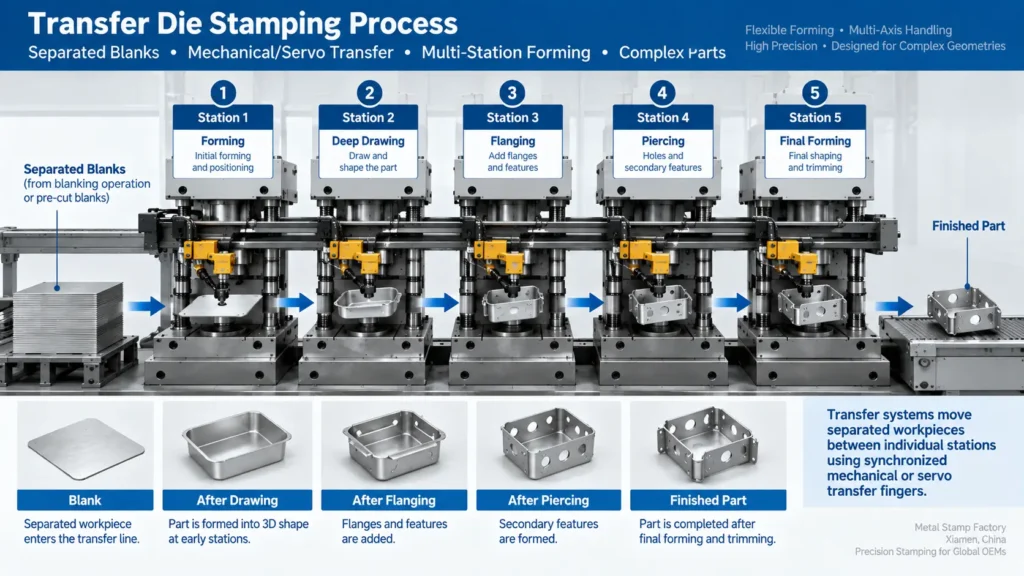
In transfer die stamping, the raw material is severed into an individual blank at the start of the line or fed as pre-cut blanks. Once separated, the workpiece is moved independently from one isolated die station to the next using mechanical grippers, vacuum cups, or servo-controlled transfer fingers.
Tooling Investment & NRE
Comparing non-recurring engineering (NRE) costs between progressive and transfer tooling depends on part complexity rather than a fixed process hierarchy. Progressive dies house all cutting, punching, and forming features within a single, integrated die set. Depending on the part features, a progressive die may incorporate side-action cams, precision pilot systems, and lifters, which influence machining and fitting expense.
Transfer tooling setups consist of individual die modules or separate die stations positioned along a shared press bed. While individual transfer die stations can sometimes be mechanically simpler than an equivalent all-in-one progressive tool, the total NRE must account for specialized transfer rails, custom gripper fingers, automation interfacing, and blank-feeding hardware.
Production Strategy & Press Requirements
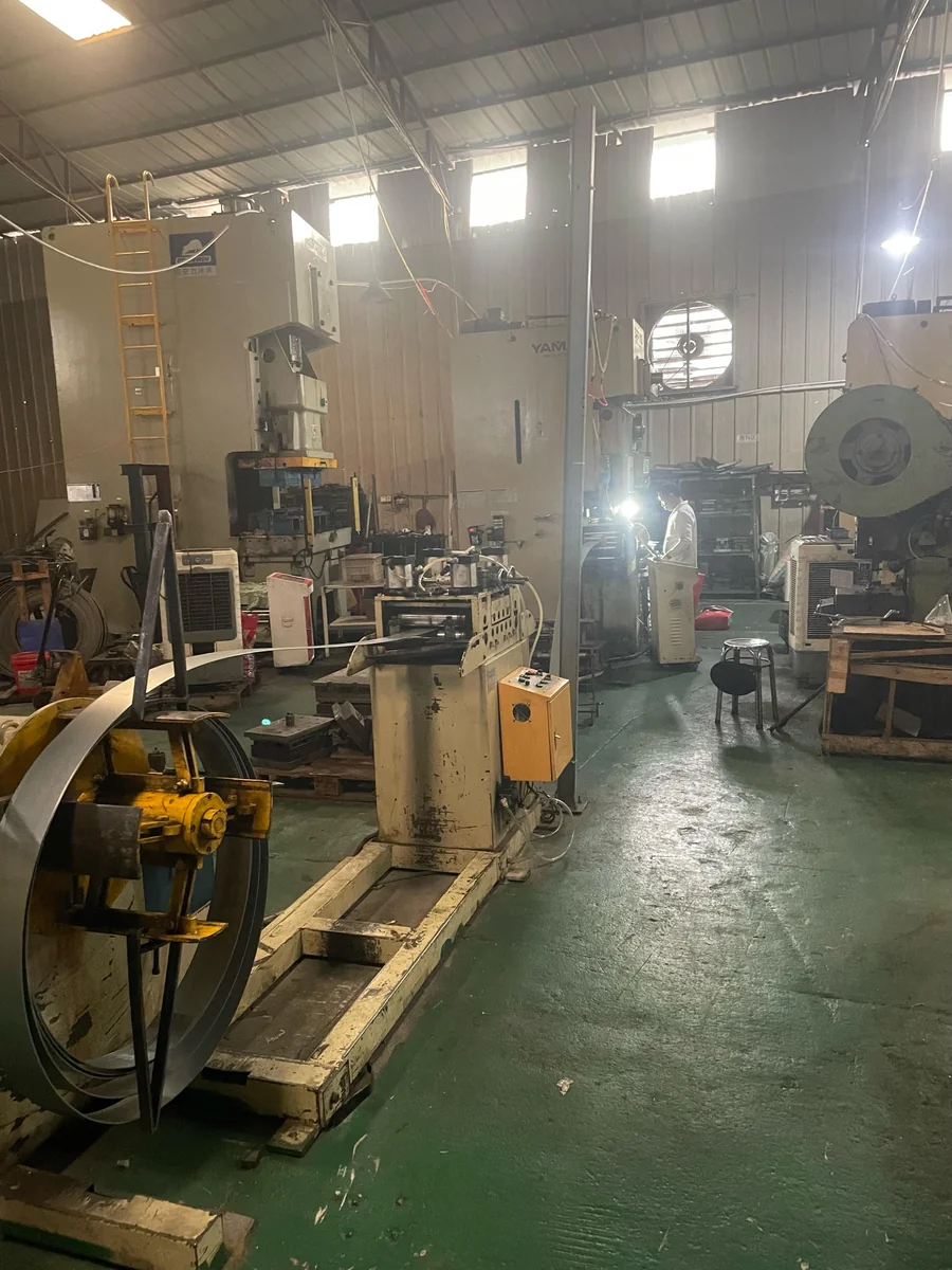
Progressive tooling is commonly integrated with presses equipped with coil handling, straightening, and feeding equipment. Material advancement relies on controlled strip feeding, so setup and process stability depend on strip alignment, feed pitch, and synchronization with the press cycle.
Transfer tooling operates with press and transfer-automation configurations designed to move separated workpieces between stations. The transfer motion must be synchronized with press movement, part positioning, and die clearance throughout the cycle.
Geometric Capability & Formability
Progressive dies are well-suited for parts where localized features, pierced patterns, and shallow forms can be produced without distorting the carrier strip. However, severe forming operations—such as deep drawing or multi-axis flanging—require careful carrier design to ensure the carrier strip maintains alignment and pitch integrity.
Transfer dies allow material to flow independently during deep forming operations because each workpiece is detached from adjacent stock. Furthermore, transfer automation allows parts to be rotated, tipped, or reoriented between stations if secondary operations require tooling access from different planes.
Understanding Progressive Die and Transfer Die Fundamentals
Automated multi-stage stamping relies on sequential operations to convert flat sheet metal into three-dimensional components. Selecting the appropriate tooling architecture establishes the foundation for part quality, tool life, and manufacturing stability.
What Is Progressive Die Stamping? (Carrier Strip Workflow)
Progressive die stamping processes continuous coil stock through a series of aligned stations within a unified tool assembly. The press feeder pushes the coil into the die by a fixed distance—the pitch—with every stroke.
Initial stations typically perform piercing, punching pilot holes, and cutting relief notches to define the outer contour of the part while preserving a continuous metal rail. Pilot pins engage the pre-punched holes in subsequent stations to locate the strip accurately before the upper die contacts the sheet metal.
As the strip advances, progressive stations perform bending, coining, embossing, or shallow drawing. The workpiece stays anchored to the carrier strip throughout these steps. At the final station, a cutoff or parting punch trims the attachment tab, releasing the completed part while the remaining web skeleton exits the press.
What Is Transfer Die Stamping? (Individual Blank Automation)
Transfer die stamping separates the workpiece from the main material stock early in the sequence. Raw material enters as coil stock or pre-cut sheet blanks. In a coil-fed transfer line, the first station punches out an individual blank, which is immediately picked up by the transfer mechanism.
The transfer mechanism consists of parallel rails fitted with custom-shaped fingers or grippers. As the press ram rises, the fingers clamp the edges of the blank, lift or slide it to the next die station, align it over the lower tooling, and retract before the ram descends.
Each station in a transfer system acts as an independent die, performing dedicated operations such as drawing, trimming, restriking, or flanging. Because the parts are disconnected from one another, station spacing can be adjusted to accommodate robust die structures or complex tooling mechanisms.
Fundamental Difference: Integrated Strip vs Mechanical Separation
The distinction between staying attached to a carrier web versus being moved as a separated blank introduces several technical considerations:
- Forming Conditions: Detached blanks in transfer dies allow unrestrained material flow during deep forming, whereas progressive parts remain connected to the adjacent carrier structure.
- Workpiece Transport: Progressive dies rely on the tensile strength and flatness of the carrier web to move the part. Transfer dies use external mechanical grippers, shifting the transport force from the sheet metal web to the transfer automation.
- Part Orientation: Progressive parts maintain a continuous spatial orientation relative to the strip feed direction. Transfer mechanisms can rotate or reorient individual blanks between stations to accommodate angled forms or multi-directional flanges when necessary.
- Scrap Generation: Progressive dies require material along the margins or center of the coil to form the carrier web. Transfer dies eliminate the carrier web, though overall material yield depends on initial blank nesting efficiency.
Material Handling and Press Automation Mechanics
How Progressive Dies Control Material Feed and Pitch
Precision material control in a progressive die relies on the interaction between an external servo feeder and internal tool pilots. The servo feeder advances the continuous metal coil into the tool by the designated pitch distance.
Because minor variations in feed length can accumulate across multiple stations, progressive tools use tapered pilot pins mounted in the upper die shoe. As the press ram descends, these pilots enter precision holes pierced in the carrier strip during the initial press stroke. The tapered entry aligns the strip to its position before forming or cutting punches engage the stock.
For this system to function reliably, the carrier strip must maintain sufficient rigidity and flatness throughout the press stroke. If severe forming operations create internal stresses that bow, twist, or stretch the carrier web, pilot alignment deteriorates, which can impact pitch precision and tool engagement.
Mechanical and Servo Transfer Systems in Transfer Presses
Transfer systems move individual workpieces using mechanical linkages tied to the press drive or programmable servo motors.
In mechanical transfer presses, the movement of the transfer rails is directly driven by cams connected to the press crankshaft. This creates a synchronized motion profile where finger clamping, lifting, advancing, placing, and returning occur in direct proportion to the ram angle.
Servo transfer systems offer operational adjustability. Independent servo drives control the movement of the transfer rails in multiple axes. Engineers can program motion profiles, adjust lift heights to clear high die obstacles, alter clamp forces for sensitive materials, or coordinate timing with secondary in-die operations.
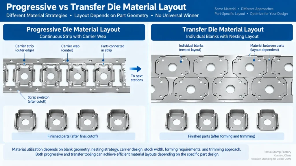
Carrier Strip Scrap vs Individual Blank Nesting Efficiency
Raw material utilization is a critical component of unit part cost over production runs. Evaluating scrap generation requires analyzing how material is arranged before and during forming operations.
| Factor | Progressive Die | Transfer Die |
|---|---|---|
| Material Format | Continuous coil with carrier strip | Individual blanks from coil or sheet |
| Scrap Source | Carrier rails, center webs, attachment bridges | Blank perimeter scrap and nesting loss |
| Optimization Method | Strip layout, pitch optimization, part interlocking | Blank nesting and material arrangement |
| Key Advantage | Efficient continuous feeding and high automation | Flexible blank utilization for complex shapes |
Progressive dies require a continuous carrier skeleton—such as side rails, center webs, or stretch bridges—to transport the part through the die. The width and thickness of these carrier rails must be sized to withstand feed acceleration and forming forces without distorting.
Transfer dies do not require a continuous carrier web. This allows material layouts to focus on optimizing initial blanking efficiency. Wide coil stock can be used to punch interlocking, angled, or trapezoidal blanks in a zig-zag pattern, optimizing material yield per coil.
However, transfer dies are not inherently more material-efficient than progressive dies in every application. On compact or intricately shaped components, a well-designed progressive strip layout with tight part interleaving can achieve raw material yield comparable to a transfer setup.
Part Size, Geometry, and Deep Drawing Constraints
Part Dimensions, Weight, and Carrier Strip Feasibility
Physical dimensions, workpiece weight, forming forces, and mechanical handling requirements dictate whether a component is viable on a progressive carrier strip or better suited for transfer automation.
As a component grows in size and weight, the carrier web connecting it to the main strip must carry greater dynamic loads during feed acceleration. If the structural capacity of the carrier rail is insufficient relative to the part mass and pitch velocity, the strip may sag or twist, affecting pilot positioning and die clearance.
When carrier strip stability cannot be maintained within acceptable tolerances, moving individual workpieces via mechanical transfer grippers removes the dependency on a continuous sheet-metal web to carry the part through the press sequence.
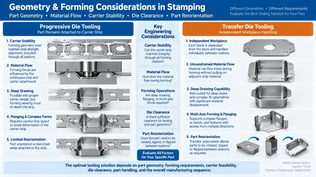
Handling Deep Drawing, Flanging, and Multi-Axis Rotation
Deep drawing involves pulling flat sheet metal into a hollow three-dimensional shape using a punch and draw ring, requiring uniform material flow from the surrounding blank.
In a progressive die, drawing material inward creates localized tension on the adjacent carrier strip. If not properly isolated using relief cuts or stretch webs, this tension can distort the carrier web and pull adjacent stations out of pitch alignment. Additionally, the vertical clearance required for deep forms must be managed to ensure the strip clears lower die elements during advancing.
Transfer tooling can provide additional workpiece-handling flexibility for drawing and multi-stage forming through several operational characteristics:
- Unrestrained Material Flow: Detached blanks allow material to draw uniformly from edges without pulling against an attached carrier framework.
- Vertical Clearance Management: Transfer automation can lift a deep-drawn shell over lower die tooling, facilitating progression to subsequent stations.
- Flexible Orientation: Components requiring angled flanging, side piercing, or undercut operations can be reoriented between transfer stations using articulated grippers to allow optimal punch access.
When Geometry Forces Part Detachment Before Final Stations
Specific geometric requirements influence whether a part can remain attached to a continuous strip or benefits from early separation:
- Perimeter Trimming Requirements: Designs requiring complete 360-degree edge trimming or peripheral edge rolling reduce the available area for carrier attachment tabs.
- Opposing Flange Orientations: Severe upward and downward bends occurring across opposite edges of a part can interfere with the horizontal feed path of a continuous strip.
- Symmetric Draw Shells: Uniform circular cups require balanced circumferential material flow; attached carrier webs introduce asymmetrical restraint that must be managed to prevent localized thinning or wrinkling.
Tooling Design, NRE Costs, and Press Capital
Die Construction, Station Count, and NRE Tooling Investment
Non-recurring engineering (NRE) costs for stamping tooling depend on component complexity, station count, die dimensions, and functional mechanisms rather than a simple rule of process selection.
Progressive dies consolidate operations within a unified upper and lower die shoe assembly. While this provides a single integrated tool set, incorporating side-action cams, complex spring lifters, precision pilot systems, or insertable carbide components increases tool design and manufacturing hours.
Transfer die setups utilize individual die modules mounted sequentially on sub-plates or press bolsters. While individual transfer stations can be structurally straightforward, total NRE incorporates the complete set of station dies, specialized transfer rails, custom gripper finger tooling, and part-detection sensor integration.
| Cost Factor | Progressive Die | Transfer Die |
|---|---|---|
| Die Structure | Integrated multi-station die assembly | Multiple independent die modules |
| Tooling Cost Driver | Station count, cams, lifters, precision pilots, inserts | Number of stations, transfer hardware, grippers, automation integration |
| Engineering Complexity | Focused on strip layout and station sequencing | Focused on station coordination and workpiece transfer |
| Maintenance Consideration | Integrated components may require specialized servicing | Individual stations may simplify access but transfer systems add maintenance requirements |
Press Machinery Requirements: Coil Feeders vs Transfer Systems
The capital equipment utilized for each tooling style differs in press infrastructure and automation integration:
- Progressive Press Setup: Progressive tooling is commonly paired with press systems incorporating coil handling, straightening, and controlled feeding equipment. The required press configuration depends on die size, forming loads, feed pitch, material characteristics, and production requirements.
- Transfer Press Setup: Transfer tooling requires a press and automation arrangement capable of moving separated workpieces between stations while maintaining adequate die clearance and positioning control. Equipment requirements depend on station layout, part geometry, forming loads, transfer motion, and the selected automation architecture.
Maintenance, Tool Wear, and Lifecycle Overhead
Tool maintenance strategies vary based on the physical structure of progressive and transfer tooling assemblies:
Progressive Tool Maintenance: Because multiple stations are integrated within one die assembly, maintenance planning must consider how individual punches, inserts, lifters, and station components can be accessed or replaced. Depending on the tool’s modular design and the repair required, servicing may be performed in the press or may require removing the die for bench maintenance.
Transfer Tool Maintenance: Individual transfer stations may provide more independent service access depending on the tooling layout. However, the transfer mechanism—including grippers, actuators, linkages, sensors, and positioning components—adds additional maintenance and alignment requirements.
Production Economics and Lifecycle TCO
Press Speeds (SPM) and Production Throughput
Operating speed—measured in Strokes Per Minute (SPM)—depends on transfer motion profiles, part handling stability, forming severity, and press/automation configurations.
In suitable applications, progressive dies can support high operating SPM because material advancement is integrated with continuous strip feeding. Achievable speed still depends on feed pitch, carrier stability, forming severity, material behavior, die design, press characteristics, sensing, and quality requirements.
Transfer die operating speeds are governed by the mechanical and physical dynamics of part transport. The motion cycle of clamping, lifting, advancing, placing, unclamping, and returning the transfer rails introduces dynamic forces on the workpiece. Operating speeds are set to ensure parts remain securely clamped and accurately positioned throughout the transfer sequence without slipping.
However, theoretical stroke rate is only one component of net production output. Overall efficiency is influenced by press uptime, strip stability, sensor reliability, and raw material quality across both tooling configurations.
Material Utilization and Life-of-Program Cost Impact
Raw material costs represent a significant lifecycle cost factor in high-volume stamping programs. Evaluating material efficiency requires analyzing raw stock consumption relative to finished component mass over the entire contract volume.
Even minor adjustments in carrier rail width or blank nesting density can yield meaningful financial impact when scaled across high production quantities. While transfer dies eliminate carrier web scrap, progressive layouts utilizing optimized blank interleaving or dual-part carriers can achieve competitive material utilization. Material yield calculations must be performed specifically for each part design.
Total Cost of Ownership (TCO) Evaluation
Evaluating Total Cost of Ownership (TCO) allows engineering and procurement teams to compare tooling options across the full lifecycle of a program.
Total Program Cost = Initial NRE + (Production Volume × Unit Part Price) + Maintenance & Setup Overhead
A thorough TCO analysis accounts for the following factors:
- Amortized Tooling NRE: Initial die design, fabrication, and tryout costs spread over the total planned production volume.
- Raw Material Expenditure: Gross sheet metal consumption per component, factoring in scrap recovery values.
- Machine Operating Rates: Press running costs, reflecting machine tonnage, bed size, and specialized transfer automation requirements.
- Secondary Operations: Costs associated with any post-stamping trimming, deburring, or reorientation operations required by a specific tool design.
- Tool Maintenance and Setup: Expected maintenance downtime, tool sharpening intervals, component replacement, and press changeover times.
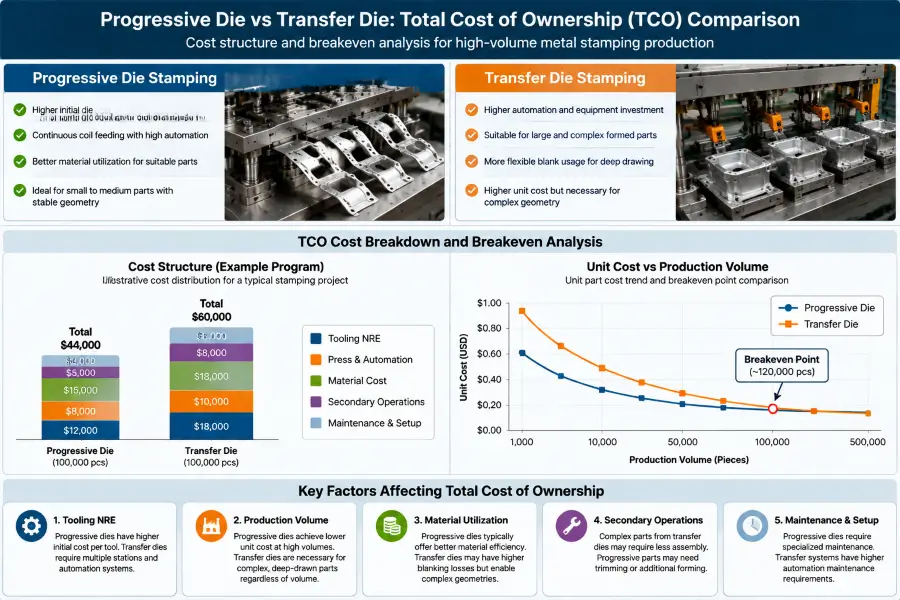
The stronger TCO depends on the interaction between tooling NRE, material utilization, achievable production throughput, press and automation requirements, maintenance, secondary operations, and the expected program lifecycle. Progressive tooling may provide economic advantages when stable carrier-based production integrates operations efficiently, while transfer tooling may provide advantages when independent workpiece handling simplifies forming or improves the overall manufacturing sequence. The comparison should therefore be modeled for the specific component rather than inferred from tooling type alone.
OEM Decision Framework: Selecting Progressive vs Transfer Tooling
5-Step Engineering Decision Matrix
If the component is primarily a flat stamped part and the decision is between multi-station sequential processing and simultaneous cutting in one station, see our progressive vs compound die tooling comparison.
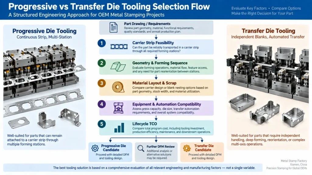
To evaluate whether a progressive die or a transfer die is appropriate for a new stamping program, engineering teams can follow a structured five-step decision process:
- Carrier Strip Feasibility Analysis: Evaluate part mass, material thickness, strip pitch, and dynamic feeding forces. Determine whether the workpiece can maintain dimensional stability on a carrier strip without twisting, sagging, or distorting pilot alignment.
- Geometric and Forming Sequence Review: Assess draw depths, flange directions, edge trimming requirements, and spatial orientation. Determine whether the forming sequence requires unrestrained material flow, 360-degree trimming, or multi-axis part rotation between stations.
- Material Nesting and Scrap Optimization: Develop comparative strip and blank layouts. Compare the gross material consumption of a progressive strip (including carrier web) against an optimized blank nesting strategy for transfer feeding.
- Equipment and Automation Compatibility: Audit available press machinery for bed dimensions, stroke length, tonnage capacity, coil feeding limits, and linear transfer automation capabilities.
- Lifecycle TCO Modeling: Calculate the total cost profile over the expected program lifespan, balancing initial tooling NRE, hourly press rates, material yield, operating speeds, and long-term maintenance overhead.
| Question | Progressive Die | Transfer Die |
|---|---|---|
| Part Size | Small to medium parts with stable carrier support | Larger or heavier components |
| Forming Requirement | Piercing, bending, shallow forming | Deep drawing, complex flanges, multi-axis forming |
| Production Volume | High-volume continuous production | High-volume complex components |
| Material Strategy | Coil strip with optimized carrier layout | Flexible blank nesting |
| Equipment Requirement | Coil feeder and progressive press setup | Transfer press and automation system |
When Progressive Die Is Often the Better Fit
Progressive die tooling is typically indicated when:
- Carrier strip feasibility analysis confirms stable workpiece transport across all stations at expected feed accelerations.
- Part geometry consists primarily of shallow forming, pierced feature arrays, and localized bends.
- Higher cycle speeds can be leveraged on standard coil-fed press equipment.
- The component maintains a uniform orientation relative to the feed direction throughout the forming sequence.
- Carrier web material consumption remains within acceptable parameters relative to total material cost.
When Transfer Die Is the More Practical Choice
Transfer die tooling is typically indicated when:
- Part mass, dimensions, or feed dynamics make stable carrier-strip transport difficult to maintain through the required forming sequence.
- Severe deep drawing or tall vertical features require unrestrained material flow and increased vertical tooling clearance.
- Part features require reorientation, tilting, or multi-axis flipping between forming operations.
- Independent blank nesting provides a meaningful material yield advantage over a continuous carrier strip layout.
- Full perimeter trimming or continuous edge forming prevents the use of a carrier attachment tab.
Frequently Asked Questions
Is progressive die tooling always cheaper than transfer die tooling? No. Tooling cost is determined by part geometry, forming complexity, station count, and tool construction standards rather than the transfer mechanism alone. A progressive die featuring multiple cam sliders, lifter mechanisms, and specialized inserts can involve higher engineering and fabrication costs than a multi-station transfer tool set.
Can deep-drawn parts be manufactured in a progressive die? Yes. Drawn components can be produced in progressive dies when the strip layout, carrier design, material behavior, forming sequence, and available die clearance can support the required material flow. Relief features or carrier designs may be used to isolate forming stresses from the strip. As forming severity and material displacement increase, maintaining carrier stability and station alignment can become more challenging, so transfer handling may also be evaluated. There is no universal draw-depth threshold that determines the choice.
Which process yields better raw material utilization? Material efficiency depends on part geometry, material thickness, and layout design. Transfer dies eliminate the continuous carrier web and allow flexible blank nesting across wide coils. However, for compact or interlocking part geometries, progressive strip layouts can achieve comparable material utilization.
What technical factors restrict a part from being stamped in a progressive die? A component may not be suitable for progressive processing if workpiece mass causes carrier web sagging, if deep drawing severely distorts the strip, if 360-degree perimeter trimming eliminates attachment tabs, or if the part must be reoriented between operations to complete required features.
Can a progressive die part be converted to a transfer die later in the program lifecycle? Potentially, but the change should be treated as a new tooling and DFM evaluation rather than a simple conversion of the existing die. The blank strategy, carrier attachments, forming sequence, station layout, workpiece handling, press and automation requirements, and qualification plan may all need to be reconsidered. Whether the change is technically and economically justified depends on the reasons for the transition and the remaining program lifecycle.
Conclusion
Selecting between progressive die and transfer die stamping requires an engineering evaluation of how part geometry, material movement, forming sequences, press automation, and lifecycle economics interact. Rather than treating either tooling architecture as a default choice, OEM engineering and procurement teams achieve optimal results by evaluating the technical requirements of the component against the operational capabilities of each system.
For detailed DFM evaluations, strip layout analysis, or tooling recommendations for custom metal stamping programs, contact the engineering team at Metal Stamp Factory in Xiamen, China.