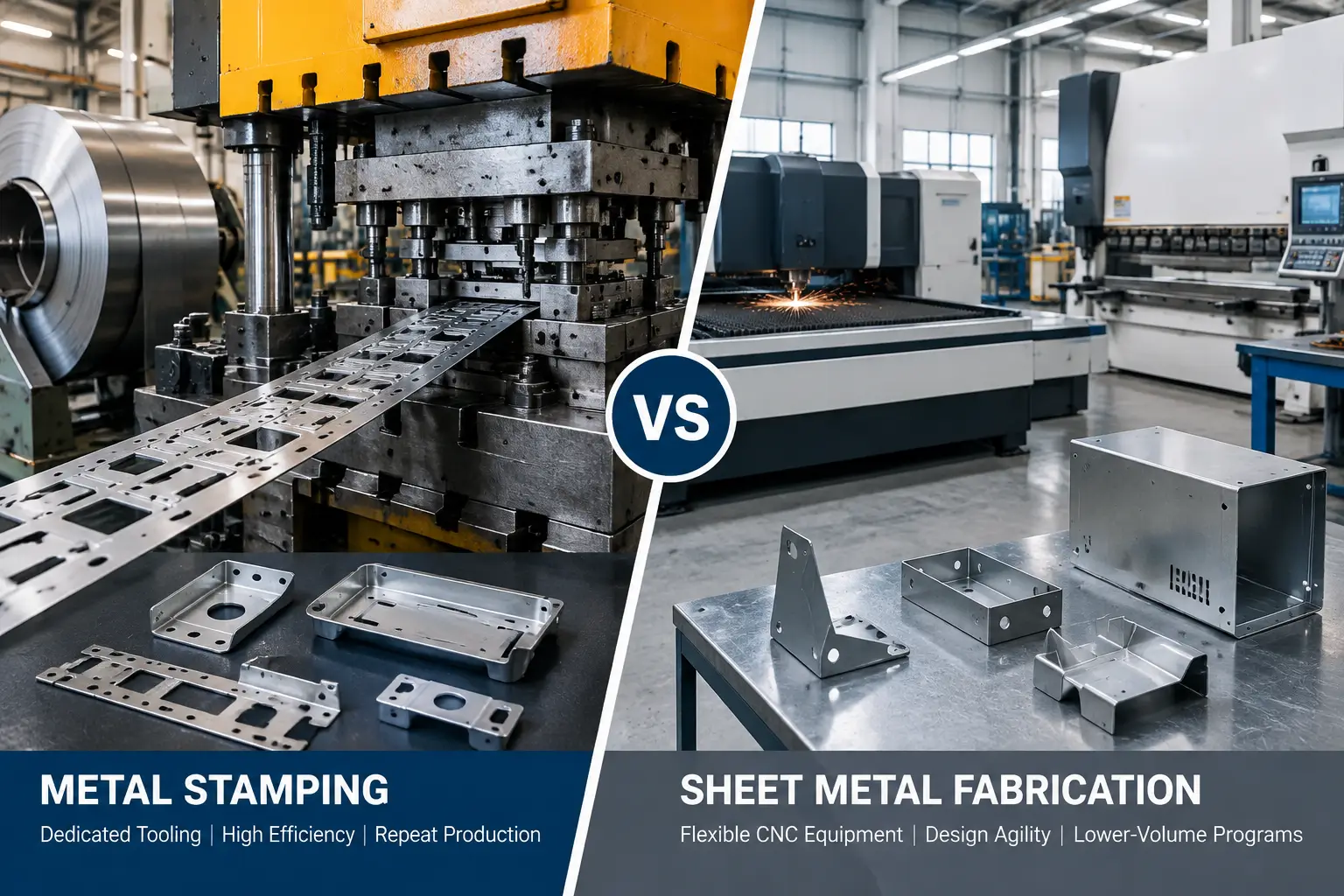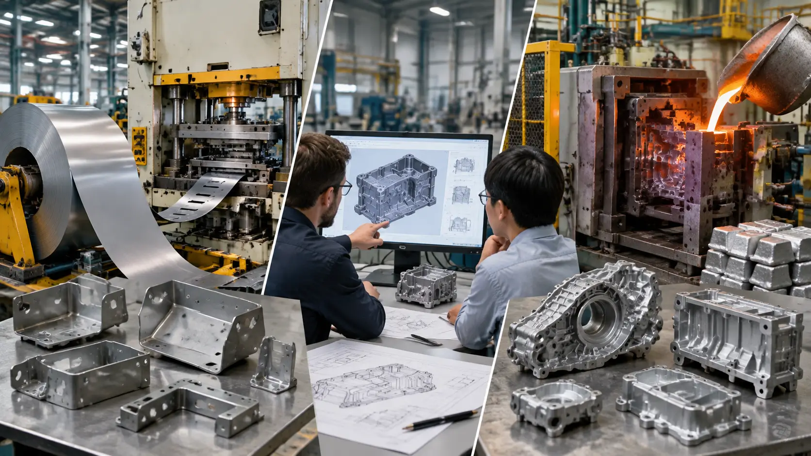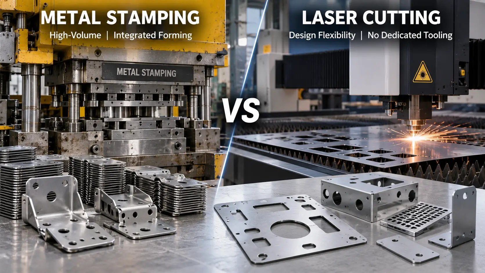
Identifying and resolving metal stamping defects is a critical aspect of maintaining quality, controlling scrap rates, and keeping manufacturing lines running efficiently. During the stamping process, raw sheet metal is converted into components through cutting, bending, forming, and drawing operations. Because sheet metal responds to physical forces, friction, and mechanical restraint, even minor variations in the setup can lead to part discrepancies.
Defects rarely stem from a single, isolated problem. In progressive die stamping or transfer die operations, a defect is often the result of multiple interacting factors involving tooling condition, material consistency, press mechanics, strip feeding, and lubrication. Diagnosing a quality issue requires an understanding of how these variables influence part geometry and surface integrity.
This guide provides an overview of physical metal stamping defects, their likely root causes, and initial prevention strategies. It is designed to help OEM buyers, quality engineers, manufacturing engineers, and sourcing managers evaluate part discrepancies, troubleshoot production problems, and route complex issues to the appropriate root-cause investigation.
What Causes Metal Stamping Defects?
Understanding the primary drivers of quality issues allows engineering and quality teams to systematically narrow down troubleshooting efforts. Many sheet metal stamping defects can be investigated through four primary operational areas.
Tooling and Die Condition
Tooling is the central element of any metal stamping process. The condition, design, and alignment of punches, dies, and station inserts directly influence the dimensional accuracy and edge quality of the finished part.
- Worn Cutting Edges: Over extended production runs, punch and die cutting edges gradually lose their sharpness. Dull edges roll the material rather than shearing it cleanly, leading to burrs and heavy rollover.
- Unsuitable Punch-to-Die Clearance: Clearance is the physical distance between the punch cutting edge and the die opening edge. If clearance is too tight, it increases cutting forces and can cause secondary shear zones. If clearance is too loose, the material rolls into the die cavity, creating excessive burrs and edge distortion.
- Die Alignment and Guide Bushing Wear: Misalignment between the upper and lower die shoes can cause uneven cutting clearance across the part geometry, leading to localized burrs or premature tool wear.
- Tooling Surface Condition: Scratches or rough grinding marks on forming inserts can transfer onto the stamped part, leading to cosmetic marks or localized strain concentration.
Material Properties and Variation
Sheet metal raw material exhibits inherent physical and mechanical variations, even within the same alloy grade or coil batch.
- Thickness Variation: Mill tolerances allow slight variations in sheet thickness across a single coil or between different material lots. Unintended increases in thickness raise forming pressures, while thinner material may reduce blank-holder resistance and induce wrinkling.
- Ductility and Elongation: Material ductility determines how much deformation a metal can withstand before necking or splitting. Lower ductility batches may crack during deep drawing or tight bending operations.
- Strength and Hardness: Yield strength and tensile strength govern how the metal flows and recovers after forming. Variations in hardness directly impact springback behavior and punching forces.
- Grain Direction and Anisotropy: Rolled sheet metal has a distinct grain direction. Depending on the material and forming geometry, bending parallel to the rolling direction can increase the risk of cracking compared with other orientations.
Press Setup and Feeding
Even precision-built tooling can produce defective parts if the press setup is inconsistent or if the raw material strip is improperly managed.
- Setup Consistency: Variations in shut height settings or clamping torque can shift forming dimensions between production runs.
- Strip Alignment and Guiding: Stock guides must maintain proper alignment as the metal strip enters the die. Misalignment causes uneven trimming and feature location errors.
- Feeding and Progression Accuracy: Automated strip feeders must advance the material by an exact pitch during each stroke. Overshooting or undershooting the progression causes pilot punches to pull the strip, leading to distorted features.
- Tonnage Distribution: Off-center loading or unbalanced press forces can cause bolster deflection, resulting in depth variations or unstable forming conditions.
Lubrication and Surface Contact
Lubrication helps control friction, manage heat, and reduce direct metal-to-metal contact between the sheet and die components.
- Friction Control: Insufficient lubrication increases friction, preventing the sheet metal from flowing smoothly into forming cavities. This restraint can cause localized thinning, necking, and tearing.
- Lubricant Application Consistency: Uneven lubricant distribution—such as dry spots on the coil—creates localized variation in material flow and surface appearance.
- Material Pickup: Without an adequate lubricating film, metal particles from the strip can adhere to the tool surface under high pressure, leading to galling and longitudinal scoring.
- Scoring and Galling Risk: High-pressure forming areas require proper lubrication management to mitigate surface degradation.
Root Cause Overview
| Root Cause Area | What Can Change | Typical Defect Clues |
|---|---|---|
| Tooling & Die | Wear, clearance, alignment, surface condition | Burrs, scoring, dimensional drift |
| Material | Thickness, strength, ductility, surface condition | Cracking, springback, wrinkling |
| Press & Feeding | Setup, strip alignment, feed progression | Position errors, inconsistent forming |
| Lubrication & Contact | Friction, lubricant coverage, material pickup | Galling, scratches, tearing |
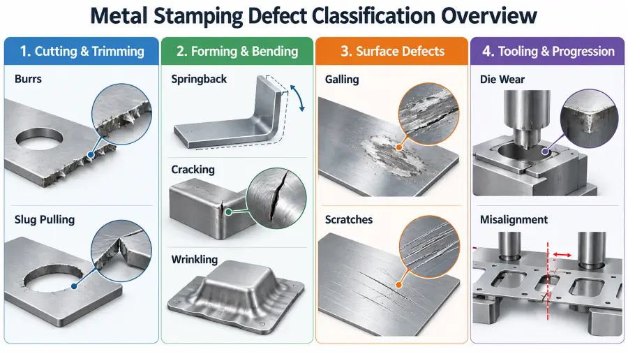
Cutting and Trimming Defects
Cutting operations, including blanking, piercing, notch-cutting, and trimming, separate the raw material using shear stresses. Discrepancies in these operations affect fit, finish, and structural performance.
Burrs and Rough Cut Edges
What It Looks Like
A burr is a raised, rough edge or small ridge of material remaining along the cut boundary of a stamped part. Rough cut edges may display jagged shear zones, heavy rollover, or double shear lines instead of a clean burnish zone.
Likely Causes
- Worn Cutting Edges: Dull punches and die cavities fail to induce a clean fracture, extruding a burr along the cut line.
- Unsuitable Punch-to-Die Clearance: Incorrect clearance shifts the fracture lines, preventing them from meeting cleanly. Excessive clearance rolls the material, while tight clearance causes secondary shearing.
- Tooling Misalignment: Wear in guide components can shift the punch off-center, creating an uneven burr profile.
- Material Differences: Softer material batches exhibit higher elongation, which can increase rollover and burr formation under standard settings.
Initial Prevention and Troubleshooting Direction
- Inspect cutting punch edges and die buttons for wear or edge rounding.
- Verify punch-to-die alignment and guide components.
- Confirm that the raw material thickness and properties fall within the specified engineering ranges.
Note: For a deeper analysis of burr formation mechanisms and process troubleshooting, see: Why Do Burrs Form in Metal Stamping? Causes and Solutions.
If your question is whether a burr is acceptable rather than why it formed, see our guide to burr tolerance requirements.
Slug Pulling and Retained Scrap
What It Looks Like
Slug pulling occurs when the scrap piece (slug) created during a piercing stroke fails to fall through the die cavity, sticking to the returning punch and drawing back onto the top surface of the material strip.
Possible Effects
- Surface Indentations: The pulled slug is pressed into the raw sheet metal strip on the subsequent press stroke, leaving deep indentations on finished parts.
- Repeated Surface Damage: Trapped scrap can mark multiple trailing parts in a progressive sequence.
- Die Interference: Retained scrap can alter forming clearances and lead to tool damage or production interruptions.
Initial Troubleshooting Direction
Review punch and die condition, slug removal behavior, lubrication, and whether the issue repeats at the same station.
Forming and Bending Defects
Forming operations bend, draw, or stretch sheet metal into three-dimensional geometries. Defects in these steps affect part shape, mechanical strength, and dimensional tolerances.
Springback and Angle Variation
What It Looks Like
Springback is the elastic recovery of sheet metal after the forming load is removed. When the punch retracts, the bent angle unbends slightly or a contoured wall flattens, causing the finished component to deviate from the intended tooling geometry.
Contributing Factors
- Material Yield Strength: Higher yield strength materials store more elastic energy during forming, resulting in greater springback.
- Bend Geometry: Larger bend radii relative to sheet thickness increase elastic recovery.
- Tooling Condition: Wear on forming inserts can alter the effective radius and influence springback consistency.
Initial Review Direction
Review the material specification and available material documentation for relevant strength or property differences, then check setup consistency and tooling condition.
Cracking, Splitting, and Tearing
What It Looks Like
Cracking and splitting present as visible fractures, micro-cracks along outer bend radii, or complete wall separation in deeply drawn or stretched regions.
Contributing Factors
- Material Ductility: If the strain required exceeds the elongation limits of the material grade, splitting can occur.
- Localized Strain Concentration: Tight inside bend radii or sharp feature transitions concentrate stresses and encourage cracking.
- Grain Orientation: Bending sheet metal parallel to its rolling grain structure increases the likelihood of fracture along the bend line.
- Process Conditions: Insufficient lubrication or excessive material restraint restricts smooth material movement.
Initial Troubleshooting Direction
Verify whether cracks align with the material rolling direction, inspect die radii for surface roughness that restricts material flow, and review blank-holding conditions.
Wrinkling and Buckling
What It Looks Like
Wrinkling appears as waves, folds, or ripples in compressive areas of a formed component, such as deep-drawn side walls or flange radii.
Contributing Factors
- Compressive Instability: When sheet metal is drawn into a smaller perimeter, compressive stresses develop that can cause the material to buckle outward or inward.
- Forming Support Conditions: Inadequate blank-holding force allows unsupported material to lift and wrinkle before entering the die cavity.
- Tooling Clearance: Excessive clearance in drawing zones leaves material unsupported, promoting compressive buckling.
Initial Review Direction
Inspect blank-holder surfaces for uniform contact, check forming clearances in draw zones, and review lubricant application in holding areas.
Surface Defects in Metal Stamping
Surface integrity is vital for functional sealing interfaces, cosmetic enclosures, and painted or plated assemblies.
Galling and Material Pick-Up
What It Looks Like
Galling is a form of severe adhesive wear characterized by surface roughness, localized material transfer, or metallic lumps welded onto forming tool surfaces. On the stamped part, it manifests as heavy longitudinal scoring or torn surface material.
Mechanism and Contributing Factors
Under high contact pressure and friction, protective surface films break down. Bare metal-to-metal contact between the strip and tool inserts leads to microscopic material transfer. Once material pickup begins, it accelerates scoring on subsequent strokes.
Initial Troubleshooting Actions
Inspect contact areas on tooling for metal buildup, clean and polish affected die inserts, and review lubrication coverage to maintain an effective barrier film during forming.
Scratches, Scoring, and Tool Marks
What It Looks Like
Scratches and scoring are linear surface indentations or grooves. Tool marks appear as impression lines or uneven burnish areas on flat part faces.
Contributing Factors
- Foreign Debris: Contamination trapped between the sheet metal and die surfaces causes intermittent scratches.
- Rough Tooling Surface Finish: Unpolished die radii or machining marks leave impression lines on formed surfaces.
- Material Handling: Scratches can occur outside the die during coil feeding, part transfer, or secondary handling.
Diagnostic Approach
Determine whether marks repeat in the exact same location (pointing to die surface or station issues) or appear intermittently (suggesting contamination or handling factors).
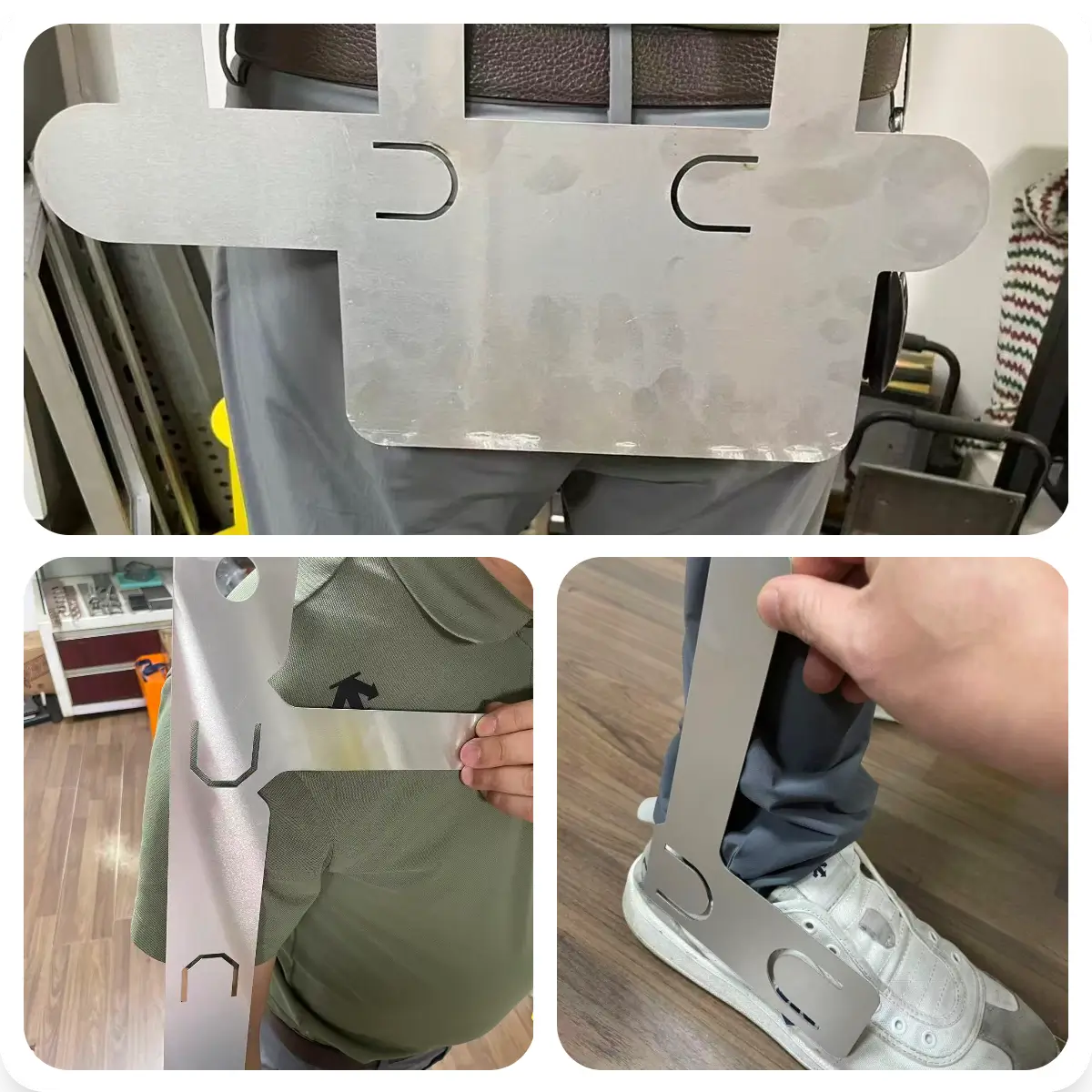
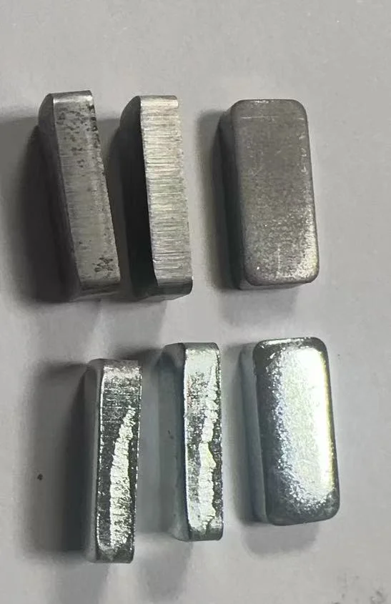
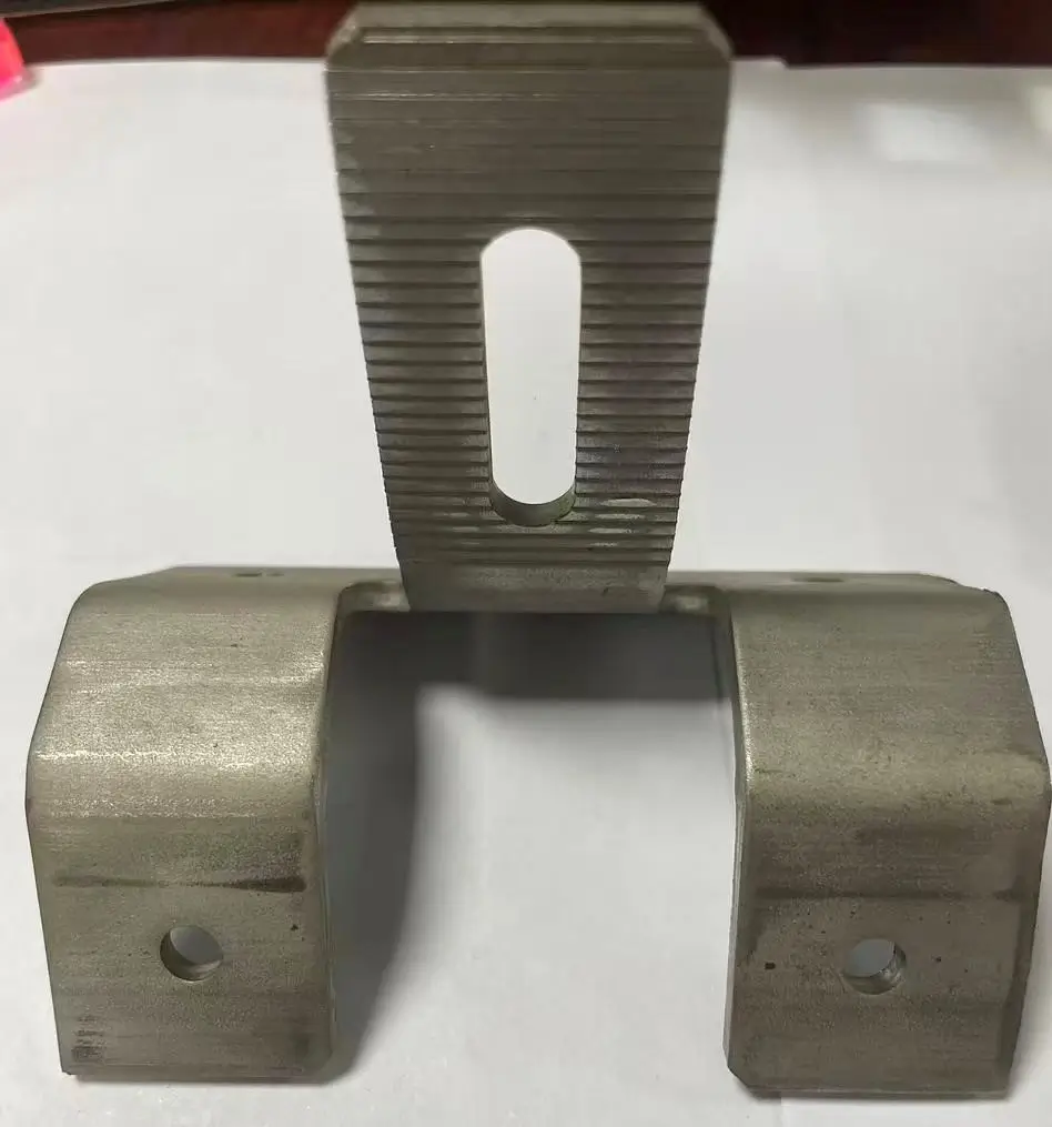
Real Production Example: Surface Marks on a W-Shaped Solar Roofing Bracket
This photo shows a W-shaped stamped bracket from a previous Metal Stamp Factory production case. The bracket was stamped from DX51D+ZM275 zinc-magnesium-coated steel coil, with the metallic coating already present on the incoming material before stamping; it was not applied as a separate post-stamping coating operation. The bracket was used in a solar roofing application with color-coated steel roof panels. Visible forming or tool-contact marks can be seen on the stamped surfaces after forming.
This type of real production example is useful because a visible surface mark should not automatically be classified as galling or assigned to a single root cause from appearance alone. Similar marks can be associated with tool contact, friction, material condition, lubrication, debris, or handling. A practical review starts by checking whether the marks repeat in the same location, when they first appear in the process, and whether the drawing defines the affected surface as a functional or cosmetic requirement.
For OEM buyers, this distinction matters: a visible forming mark and confirmed galling are not the same diagnosis. Galling normally requires additional evidence such as material transfer, recurring scoring, or corresponding buildup on the tooling. Separating the visual symptom from the confirmed root cause helps avoid unnecessary tooling changes and keeps corrective action focused on the actual process condition.
Tooling and Progression Problems
Progressive and transfer dies rely on consistent mechanical interaction across multiple operations. Problems in tooling condition or strip progression affect the entire stamping run.
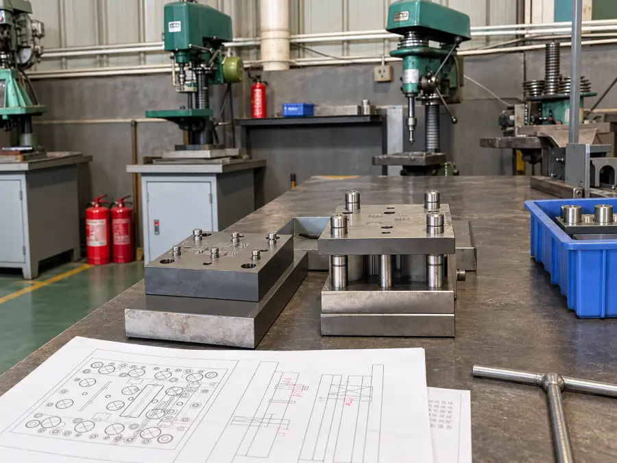
Stamping Die Wear
Stamping die wear develops as dies undergo mechanical stress, sliding friction, and cyclic impact during operation. Over time, wear changes tool geometry and alters forming performance.
#33 → #40 Internal Link
For a detailed review of wear mechanisms, warning signs, sharpening, repair, and maintenance decisions, see our guide to stamping die wear.
Warning Signs of Die Wear
- Increasing Burr Height: Shear edges lose sharpness, resulting in larger burrs along cut profiles.
- Declining Edge Quality: Rollover and fracture zones widen on cut edges.
- Dimensional Drift: Forming radii wear down, causing springback to shift and part dimensions to drift.
- Recurring Surface Marks: Wear grooves on tooling radii cause recurring scoring on formed walls.
- Forming Instability: Increased internal friction alters material flow during drawing.
Initial Troubleshooting
Identify whether symptoms worsen progressively over production cycles, inspect high-wear tooling components, and compare first-piece samples against parts produced later in the run.
Strip Misalignment and Progression Errors
In progressive die operations, the raw metal strip advances through a series of discrete stations. Accurate progression ensures each operation aligns precisely with preceding features.
Symptoms and Primary Causes
Symptoms include feature-to-feature position drift, off-center hole punching, and pilot pin impression damage. These issues may be associated with feeder settings, stock guide clearance, pilot wear, strip tension, or other progression-related factors.
Metal Stamping Troubleshooting: How to Identify the Root Cause
When a defect appears during production, following a structured diagnostic sequence helps teams isolate the root cause quickly and logically.
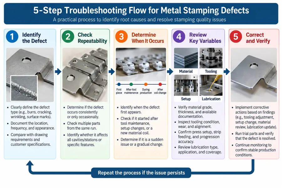
Step 1: Identify the Physical Defect
Classify the observed issue into one of four primary functional categories:
- Edge defects: Burrs, rollover, excessive fracture, split cut edges.
- Forming defects: Springback, open angles, wall cracking, flange wrinkling.
- Surface defects: Galling, scratches, die imprints.
- Tooling/Progression defects: Pitch variation, pilot punch damage, feature location drift.
Step 2: Check Whether the Defect Is Repeating or Intermittent
Observe the frequency of the issue across a consecutive sequence of stamped parts:
- Repeating defects in the same location may point toward a tooling or station-related cause, such as a damaged punch edge or die insert.
- Intermittent defects may require investigation of material variation, feeding, contamination, lubrication, or setup consistency.
Step 3: Determine When the Defect Appears
Identify operational timing associated with the defect’s onset:
- Appears during first-piece setup: May warrant checking setup parameters, shut height, and material against project requirements.
- Appears following tool maintenance: May warrant checking alignment, assembly condition, and relevant clearances.
- Develops gradually over production: May be associated with tool wear, temperature-related effects, lubrication changes, or other process variation.
- Appears after a material coil change: May warrant reviewing differences in material thickness, mechanical properties, or surface condition.
Step 4: Review Material, Tooling, Setup, and Lubrication
Conduct a broad process audit across core parameters:
- Material: Verify material grade, thickness, and available documentation against project requirements.
- Tooling: Inspect cutting punch edges, draw radii, and pilot pins for wear or pickup.
- Press Setup: Verify shut height, bolster cleanliness, and stock guide alignment.
- Lubrication: Confirm lubricant type, application method, and surface coverage.
Step 5: Correct the Cause and Verify the Result
Implement a targeted corrective change based on the primary diagnostic hypothesis. After making an adjustment:
- Produce a new trial sample batch.
- Inspect critical dimensions and edge quality.
- Compare results against agreed project requirements to verify the resolution.
For a broader overview of dimensional, visual, burr, and final checks, see our guide to metal stamping quality inspection.
Metal Stamping Defect Troubleshooting Matrix
This reference matrix summarizes common sheet metal stamping defects, their typical visual symptoms, potential root causes, and initial diagnostic directions.
| Defect | Typical Symptom | Possible Causes | Initial Troubleshooting Direction |
|---|---|---|---|
| Burrs | Raised metal edges or rough ridges along cut lines. | Worn punch/die edges; unsuitable cutting clearance; tool misalignment. | Inspect cutting edges for dullness; check punch-to-die alignment and clearance. |
| Slug Pulling | Slugs stick to punches and press into subsequent parts. | Lubricant adhesion; residual magnetism; punch face or ejection issues. | Review punch and die condition, slug removal behavior, lubrication, and station repeatability. |
| Springback | Formed angles unbend or spring open after load release. | Material yield strength variation; improper shut height; bend radius geometry. | Check material tensile properties; verify press shut height and tooling condition. |
| Cracking / Splitting | Fractures or tears along bend lines or in drawn walls. | Low material ductility; tight bend radii; bending parallel to grain; excessive restraint. | Review material elongation; check grain orientation; review blank-holding conditions and material flow. |
| Wrinkling | Wavy ripples or folds in flange areas or drawn walls. | Insufficient blank-holder force; excessive tool clearance; thin material. | Review blank-holding conditions, material flow, and punch-to-die clearances. |
| Galling | Severe longitudinal scoring and torn metal on part surfaces. | Metal-to-metal contact breakdown; inadequate lubrication; rough tool surface. | Review lubrication coverage and tool surface condition; clean transferred metal from die inserts. |
| Scratches | Fine linear grooves or intermittent marks along the part surface. | Debris in die; rough stock guides; material handling contact. | Clean die surfaces; inspect coil feeder stock guides and handling equipment. |
| Die Wear | Gradual increase in burrs, altered form angles, and edge breakdown. | High production stroke counts; abrasive raw metal; insufficient lubrication. | Inspect high-wear tool radii; evaluate edge sharpness and maintenance needs. |
| Misalignment | Off-center features, variable margins, or pilot damage. | Feeder slip; worn pilot pins; improper stock guide clearance. | Re-align strip guides; check feed progression timing; inspect pilot pins. |
How to Prevent Metal Stamping Defects Before Production Problems Escalate
Preventing quality issues requires clear communication, controlled tooling practices, and consistent process verification long before high-volume manufacturing begins.
Review the Drawing and Manufacturing Requirements
Prior to tooling fabrication or part production, quality and engineering teams should review part drawings to identify tight-tolerance features, critical bend radii, and key cosmetic requirements. Evaluating these features early helps engineers plan tooling that accounts for material flow and stress concentration risks. For broader upstream DFM considerations, see our metal stamping design guidelines.
Match Material to the Approved Specification
Raw material consistency is important for maintaining stable stamping results. Ensure incoming sheet metal coils match approved material specifications for alloy grade, temper, thickness range, and surface finish. Maintaining raw material traceability helps isolate whether production variations stem from raw stock batch differences or press equipment shifts.
Confirm Tooling Condition Before Production
Inspect active cutting punches, forming inserts, stripper plates, and pilot pins for signs of wear, chipping, or metal pickup prior to production. Maintaining punch sharpness and clean contact surfaces helps prevent burr formation and surface scoring.
Control Setup and Feeding Consistency
Maintain standardized press setup routines across production runs. Document setup parameters such as shut height, feed pitch timing, stock guide positioning, and lubricant spray settings. Consistent setup practices reduce variation caused by shifting equipment parameters.
Verify Samples Before Volume Production
For new tooling, significant adjustments, or projects that require sample approval, review representative samples before volume production proceeds. Verifying critical dimensions, edge quality, and surface condition against approved product specifications helps verify process stability.
What OEM Buyers Should Ask When Defects Keep Recurring
When persistent metal stamping defects delay shipments or cause assembly fitment issues, OEM buyers need clear, structured communication from their stamping supplier to evaluate root-cause investigations.
| Question to Ask | Why It Matters |
|---|---|
| What defect was identified? | Confirms the supplier has clearly classified the problem. |
| At which operation or die station does it occur? | Helps narrow the issue to a specific stage. |
| Is it continuous or intermittent? | Helps distinguish repeatable station-related issues from variable process factors. |
| Has the material batch or thickness changed? | Checks whether raw material variation may be contributing. |
| Was tooling condition checked? | Confirms tool wear, buildup, or alignment was reviewed. |
| What corrective action was made, and how was the result verified? | Shows whether corrective action was followed by verification. |
Understanding these diagnostic details enables buyers to engage in productive technical discussions with suppliers, evaluate proposed corrective actions, and support manufacturing stability.
Frequently Asked Questions
What are the most common metal stamping defects?
The most common metal stamping defects include edge burrs, slug pulling, springback (angle variation), cracking or splitting during forming, wrinkling in drawn walls, surface galling, scratches, die wear degradation, and strip progression misalignment.
What causes defects in metal stamping?
Metal stamping defects can be caused by interacting variations across four primary areas: tooling condition (dull edges, incorrect clearance), material properties (thickness variation, low ductility), press setup and feeding (misalignment, feed pitch errors), and lubrication (insufficient coverage, high friction).
How can metal stamping defects be prevented?
The risk of metal stamping defects can be reduced through pre-production drawing reviews, material verification, tooling inspection, consistent press setup, and sample evaluation before volume manufacturing where appropriate.
How do you troubleshoot recurring metal stamping defects?
Troubleshooting recurring defects involves a 5-step diagnostic process: identifying the defect type, determining if it is repeating or intermittent, checking when it occurs during the run, auditing material/tooling/setup/lubrication parameters, and applying a targeted corrective change followed by sample verification.
How can you tell whether a stamping defect is caused by tooling or material?
Repeating defects in the same location may point toward a tooling or station-related cause (such as a nicked punch creating a consistent burr). Intermittent defects may require investigation of material variation, feeding, contamination, lubrication, or setup consistency (such as springback shifts or localized cracking due to material hardness variations).
If you are reviewing a stamped part with recurring burrs, cracking, wrinkling, surface marks, or tooling-related issues, send us your drawing and defect photos for project review.