Stamping burrs are raised, unwanted edges or ridges of material that remain along the sheared profile after a cutting, punching, or blanking operation. During sheet metal processing, the press punch forces the metal into or through a die button to shear the stock to a specified geometry. While an ideal shearing action produces a clean edge, real-world physical factors—such as tool edge wear, improper clearance, press deflection, and material variation—can prevent clean fracture. Instead of shearing sharply, the metal stretches beyond its elastic limit and deforms past the intended cutting plane, leaving excess material attached to the edge.
Uncontrolled burr formation introduces significant operational risks in custom metal stamping and precision hardware manufacturing. Excessively raised edges can cause dimensional non-conformance, interfere with mating components during assembly, puncture wire insulation in electrical hardware, and create safety hazards for manual handlers. Furthermore, unstable burr growth often signals underlying press setup or tooling issues that, if left unaddressed, may accelerate tool damage or degrade product consistency across production runs.
Burr formation in metal stamping is rarely caused by a single, isolated variable. Instead, it is usually the result of interacting factors involving tooling condition, punch-to-die clearance, tool alignment, sheet thickness, material mechanical properties, and press setup.
Diagnosing why burrs form requires evaluating how the cut edge physically develops and analyzing specific burr patterns observed on stamped parts. This guide breaks down the physical mechanics of edge shearing, explores the primary causes of stamping burrs, presents a systematic troubleshooting methodology, and details practical press-side reduction strategies.
Note: This article focuses on the physical causes, diagnostic patterns, and process-level reduction of stamping burrs. If the primary question is whether a specific burr height complies with drawing specifications or edge acceptance criteria rather than why it formed, refer to our dedicated metal stamping burr tolerance guide.
For a broader overview of burrs alongside other common failure modes, see our guide to common metal stamping defects.
What Causes Burrs in Metal Stamping?
Stamping burrs form when the mechanical forces applied by the punch fail to produce a clean fracture across the material thickness. The underlying causes generally fall into five key operational categories:
- Tool edge condition and wear: As punch and die edges lose their sharp radius over continued production, they lose the ability to concentrate shear stress cleanly, which can cause the sheet metal to bend and stretch before fracturing.
- Punch-to-Die clearance: Unsuitable spacing between the punch and die cutting edges alters the stress distribution in the material. Both excessive and insufficient clearance can disrupt the optimal alignment of upper and lower fracture cracks.
- Punch and die alignment: Lateral shifting, tool angularity, or guide pin play can create non-uniform clearance around the perimeter of a feature, which may lead to localized or one-sided burrs.
- Material properties and sheet thickness: Variations in material ductility, tensile strength, work-hardening behavior, or coil thickness alter how the metal responds to shear stresses, shifting the fracture point.
- Press setup and feeding conditions: Inconsistent shut height, press bed deflection, improper strip guiding, or debris buildup on tool faces can introduce temporary or cyclic variations in the cutting action.
| Cause Area | How It Can Affect the Cut Edge | What to Review |
|---|---|---|
| Tool Edge Condition | Rounded cutting edges can drag and stretch metal into the clearance gap instead of cleanly initiating fracture cracks. | Punch and die edge radius, localized chipping, galling, and surface wear patterns. |
| Punch-to-Die Clearance | Non-optimal spacing alters fracture crack angles, which can contribute to secondary shearing or severe plastic tearing. | Per-side clearance relative to nominal sheet thickness, material grade, and mechanical properties. |
| Tool Alignment | Asymmetrical clearance around the perimeter can cause uneven material deformation and localized edge extension. | Guide pins, bushings, punch holder squareness, die shoe seating, and press alignment. |
| Material Properties | Highly ductile material conditions allow greater plastic deformation before fracture; thickness variations change effective clearance percentage. | Material grade, temper, thickness tolerances, and available material documentation. |
| Press & Setup Variables | Unstable strip positioning or press bed deflection under load can create inconsistent penetration and localized edge dragging. | Feeder alignment, strip lift height, stripper pad pressure, shut height consistency, and press rigidity. |
How Does a Burr Form During Metal Stamping?
To understand why burrs form, it is necessary to examine the physical sequence of events that occurs when a punch strikes sheet metal. A standard sheared edge profile consists of four distinct zones: the rollover zone, the burnish zone (shear band), the fracture zone, and the burr.
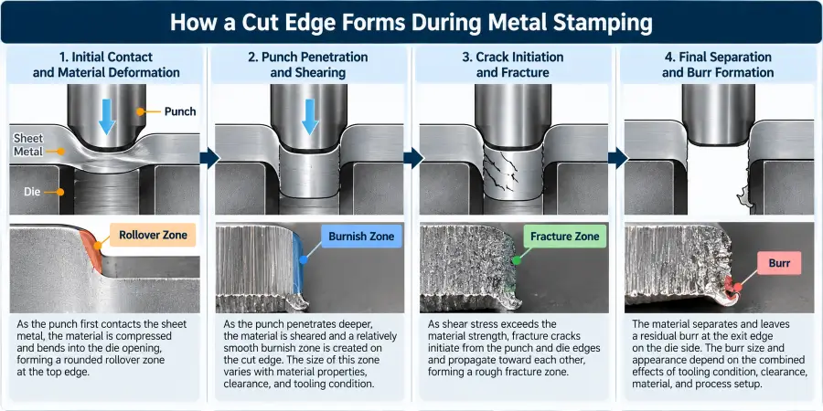
Rollover Zone
As the punch initially makes contact with the top surface of the sheet metal, the applied force causes initial elastic and plastic deformation before any actual cutting begins. The metal slightly bows and draws inward along the punch edge. This produces a smooth, slightly curved radius along the top entry edge of the stamped part known as the rollover zone. Higher material ductility or wider punch-to-die clearance generally yields a larger rollover zone.
Burnish Zone
As punch pressure continues to build, the cutting edge penetrates deeper into the sheet metal. The punch shears through the material, leaving a smooth, vertical, and shiny band along the cut profile known as the burnish zone or shear band. The relative proportion of the burnish zone across the sheet thickness is not fixed; it varies according to material properties, punch-to-die clearance, cutting-edge condition, and other process conditions.
Fracture Zone
As punch penetration reaches a critical depth, the shear stress within the material exceeds its ultimate shear strength. Microscopic cracks initiate simultaneously at the cutting edges of both the upper punch and the lower die button. In a balanced setup, these two crack fronts propagate toward each other along a slanted plane and meet. When the crack fronts unite, the remaining material fractures, completely separating the slug or part. This yields the rough, matte-textured region of the profile known as the fracture zone.
Burr Formation
A burr forms on the exit edge of the sheet—the side opposite punch entry—when the crack initiation or propagation process is disturbed. If the punch edge is rounded or the clearance gap is unsuitable, the crack fronts may fail to meet cleanly. Instead of fracturing along a defined path, the material along the exit edge can undergo localized tensile stretching. As the punch completes its downward stroke, this stretched metal tears, leaving a raised lip extending beyond the lower sheet surface.
Imperfect fracture crack alignment, worn tool edges, unsuitable punch-to-die clearance, or improper strip support can all leave residual raised material along the stamped edge.
Main Causes of Stamping Burrs
Because burrs form during the transition from shearing to fracture, any tooling, setup, or material condition that alters stress distribution at the cutting edge can directly contribute to burrs.
Worn or Damaged Cutting Edges
Tool edge wear is a common contributor to increasing burr formation in metal stamping. As a punch or die performs repeated strokes, the cutting edge can undergo abrasive, adhesive, or erosive wear, resulting in cutting edge rounding.
A rounded cutting edge can no longer concentrate shear stress along a sharp line. Instead of piercing the metal cleanly, a dull tool pushes and stretches the sheet into the die cavity. This increases the amount of plastic deformation occurring prior to crack initiation. As a result, the fracture point may be delayed, and the exiting edge can suffer localized tensile necking and tearing, leaving a raised burr.
Local tooling damage, such as minor edge chipping or micro-galling along the punch flank, can create localized burr spikes along an otherwise acceptable edge.
For a broader review of cutting-edge deterioration, warning signs, sharpening, repair, and maintenance decisions, see our guide to stamping die wear.
Incorrect Punch-to-Die Clearance
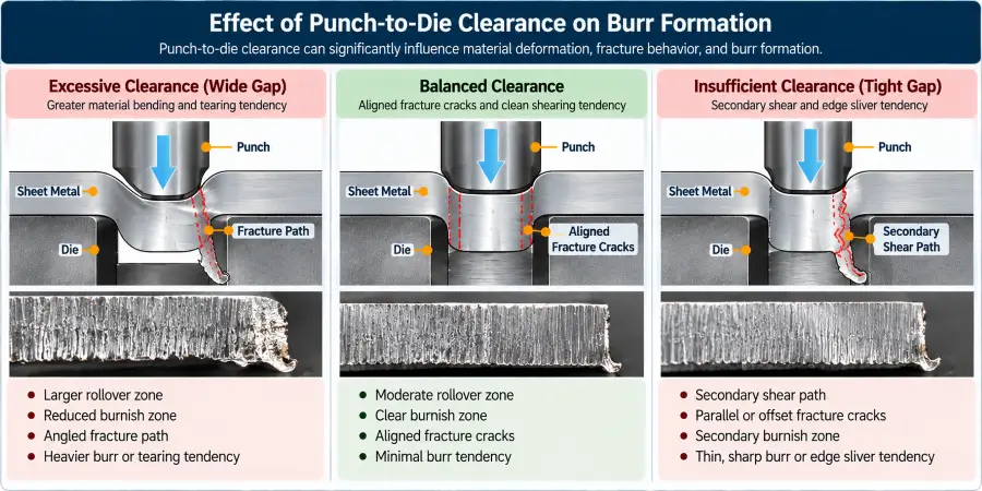
Punch-to-die clearance—the total distance or gap per side between the punch cutting edge and the die button opening—exerts a fundamental influence on edge fracture mechanics. Clearance should be evaluated relative to material type, temper, mechanical properties, and nominal sheet thickness.
- Excessive Clearance: When the gap between the punch and die button is too large, the material is subjected to increased bending and tensile stresses rather than clean shearing. This can expand the rollover zone, reduce the burnish zone, and cause the material to stretch heavily into the gap before tearing, which may leave a heavy burr along the exit side.
- Insufficient Clearance: When clearance is too tight, the fracture cracks originating from the punch and die edges may fail to align. Instead of meeting directly, the two crack paths can pass each other. The punch must then shear through the remaining material wedge between the offset cracks, a phenomenon known as secondary shear or double burnish. Secondary shear can increase required press tonnage, accelerate edge wear, and leave a thin, sharp burr or sliver on the stamped edge.
- Uneven Clearance: If clearance is wider on one side of a punch and tighter on the opposite side, the cut edge can show asymmetrical characteristics, often producing a localized burr on the wider clearance side.
For additional technical background on punch-to-die clearance and perforating behavior, see Dayton Lamina’s guide to engineered clearance.
Punch and Die Misalignment
Even when tool clearance is calculated correctly, physical misalignment between the punch and die button alters the operational clearance around the perimeter of the cut feature. Misalignment may stem from several mechanical factors:
- Inadequate or worn guide pins and bushings in the die set.
- Lateral movement or play in the press ram guides.
- Off-center loading on progressive dies causing upper shoe deflection.
- Improper mounting or alignment of individual punch inserts during die assembly.
When misalignment occurs, the punch shifts off-center relative to the die button cavity. Clearance becomes tighter on one side and wider on the opposite side, which can result in a one-sided burr on the wide-clearance edge.
Material Thickness and Mechanical Properties
The physical and metallurgical properties of the incoming raw material directly affect cut-edge quality:
- Material Ductility: More ductile material conditions may allow greater plastic deformation before fracture, which can influence rollover and burr formation unless punch-to-die clearance and edge sharpness are properly maintained.
- Thickness Variation: Raw sheet metal coils feature manufacturing tolerances in nominal thickness. If a batch of material runs on the thicker side of its specification, the effective percentage of punch-to-die clearance decreases. Conversely, thinner stock increases effective percentage clearance.
- Batch-to-Batch Mechanical Property Shifts: Variations in coil temper, grain orientation, or work-hardening behavior alter the crack propagation angle. A tooling setup optimized for one material batch may exhibit increased burr formation when a new coil with slightly different properties is introduced.
Reviewing material specifications and available material documentation helps confirm whether stock variations are contributing to edge defects.
Press Setup, Strip Position, and Local Process Conditions
Inconsistent conditions at the press can introduce variable burr formation during a production run:
- Strip Position and Lifters: If the incoming sheet metal strip is not supported flatly against the die surface, or if stock lifters fail to position the strip at the correct feed level, the punch may strike the sheet at an angle, causing uneven shear deformation.
- Inadequate Stripper Pressure: Insufficient holding force from the stripper pad allows the material to lift, buckle, or shift during punch entry and withdrawal, destabilizing the fracture zone.
- Debris and Slug Accumulation: Oil sludge, fine metal slivers, or pulled slugs trapped under the strip or between die plates can alter surface parallelism, localized press shut height, and strip alignment.
How to Troubleshoot Metal Stamping Burrs
When investigating a burr issue, the first question should not simply be “Is there a burr?” Engineers and quality inspectors should systematically evaluate where the burr appears along the profile, whether it repeats in identical locations across multiple stamped parts, and whether it increased gradually or appeared suddenly.
A Practical Diagnostic Principle
A burr pattern is a diagnostic clue, not proof of a single root cause.
Different physical underlying issues can yield similar-looking burr profiles. Therefore, observed burr patterns should be treated as guidance on where to begin press-side and toolroom inspections rather than definitive proof of a single failure mode.
| Burr Pattern | What It May Suggest | First Check |
|---|---|---|
| Burr increases gradually over production | Progressive cutting-edge rounding or uniform tool wear. | Inspect cutting edge condition on punch and die button. |
| Burr is heavier on one side of a feature | Asymmetrical clearance that may be associated with tool misalignment, punch deflection, or worn guide components. | Check punch-to-die alignment, guide pin clearance, and die shoe seating. |
| Burr appears suddenly during operation | Localized tool damage, chipped edge, loose punch retainer, or foreign object damage. | Inspect cutting edges for chipping, cracks, galling, or loose components. |
| Burr changes after a raw material change | Shifts in coil thickness, material ductility, yield strength, or temper. | Review material thickness and specification against available material documentation. |
| Burr varies around the perimeter of a feature | Inconsistent clearance along complex shapes or non-uniform tool geometry. | Review local clearance and feature condition across straight and curved sections. |
| Burr varies intermittently from stroke to stroke | Unstable strip feeding, flexing stock, inadequate stripper pad holding force, or press bed deflection. | Review setup and feeding consistency, strip lifter height, and stripper pad holding force. |
Real Production Perspective: Do Not Diagnose a Burr From Appearance Alone
In actual stamped parts, burr condition should not be diagnosed from a single edge photo alone. While an edge photograph provides visual confirmation of burr orientation and size relative to the cut profile, relying on appearance alone can lead to incorrect corrective actions.
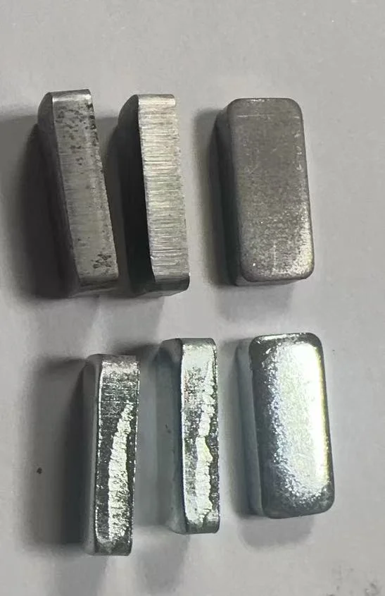
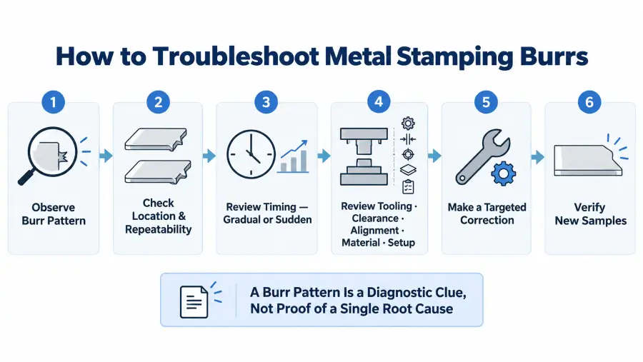
Engineers compare location, repeatability, timing, tooling condition, material documentation, and press setup evidence before assigning a root cause. A heavier burr may be associated with cutting-edge wear, improper clearance, tool misalignment, material variation, or a localized tooling condition.
Because distinct underlying issues can produce similar-looking cut edges, making immediate assumptions—such as sharpening a punch when the actual problem is a misaligned guide bushing—wastes setup time and removes tool steel unnecessarily. Where practical, make a targeted correction based on physical evidence and verify the result on new stamped samples.
Why Do Stamping Burrs Get Larger Over Time?
During continued production, the condition of the cut edge can shift:
- Cutting Edge Changes: Continued shear contact between the tool and sheet metal gradually alters the cutting edge radius over time.
- Altered Shearing Behavior: As cutting edges round or experience localized wear, shear stress concentration decreases, which can increase plastic bending and delay material fracture.
- Systematic Review: Gradual burr growth warrants tooling inspection, but material thickness, material condition, lubrication, tool alignment, and setup changes should also be reviewed to determine the primary factor.
Why Is the Burr Larger on One Side?
A burr pattern that appears heavier on one side of a feature may indicate asymmetrical cutting conditions across the profile.
This pattern can be associated with uneven punch-to-die clearance, tool misalignment, localized punch deflection under side-thrust loads, or wear in press guiding components. Repeatable one-sided location is a valuable diagnostic clue that should prompt inspection of the corresponding punch and die condition, tool centering, and guide pin alignment. However, a one-sided burr is not proof of a single root cause and warrants a review of setup and tooling evidence.
How to Reduce Burr Formation in Metal Stamping
Minimizing burr formation during stamping requires maintaining control over tooling condition, clearance geometry, alignment, and press setup.
Inspect Cutting Edges
When burr condition changes, inspect punch tips, die buttons, and cutting inserts for edge rounding, micro-chipping, adhesive galling, and flank wear. Maintaining proper edge condition promotes clean fracture crack initiation and reduces excess plastic stretching.
Review Punch-to-Die Clearance
Evaluate punch-to-die clearance in relation to material specification, mechanical properties, and nominal sheet thickness. Avoid relying on single universal clearance percentages across all jobs, as optimal clearance varies with material strength, ductility, and application requirements.
Verify Tool Alignment
Check tool alignment when burrs are localized or one-sided:
- Inspect guide pins, bushings, and wear plates for play or lateral wear.
- Verify that punch retainers and die button pockets are clean, square, and properly seated.
- Check press ram parallelism to prevent lateral displacement under load.
Review Material and Setup Changes
If burr formation increases unexpectedly, review recent operational changes:
- Check incoming material thickness against specification.
- Review available material documentation to verify coil temper and grade consistency.
- Inspect strip feeding alignment, stock lifter positioning, and stripper pad pressure to ensure the strip remains flat during the stroke.
Verify the Result With New Samples
Where practical, execute a single targeted correction, produce new stamped samples, and compare the cut-edge condition again to verify improvement against project requirements.
For a broader overview of dimensional, visual, burr, and final verification, see our metal stamping quality inspection guide.
Process Correction vs. Secondary Deburring
When addressing burrs in metal stamping, it is important to distinguish between process correction and secondary deburring:
- Process Correction: Addresses why burr formation changes or becomes excessive during stamping by inspecting and adjusting tool edges, clearance, alignment, material consistency, or press setup.
- Secondary Deburring: Removes residual burrs after stamping through post-processing operations where specific project requirements call for it.
Downstream deburring operations may be necessary depending on part function or edge specifications. However, adding a deburring step does not automatically mean the stamping root cause was corrected. When burr condition changes unexpectedly, root-cause investigation at the press should precede secondary deburring decisions.
What OEM Buyers Should Ask When Burrs Keep Recurring
When burrs recur in custom metal stamping or OEM hardware production, buyers and sourcing managers can ask targeted questions to review the troubleshooting process:
- Is the burr uniform or concentrated on one side? (Helps distinguish between general edge wear and localized clearance or alignment issues.)
- Did the burr increase gradually or appear suddenly? (Helps differentiate progressive tool wear from sudden edge damage or setup shifts.)
- Was the cutting edge condition checked? (Verifies that physical tool sharpness was inspected.)
- Were clearance and alignment reviewed for this material and thickness? (Confirms that tooling setup matches material parameters.)
- Did the material thickness or production setup change before the burr increased? (Identifies potential raw material or press-side variables.)
- What evidence supports the proposed root cause? (Promotes evidence-based diagnosis over assumptions.)
- Was the result verified after the corrective action? (Ensures improvement was confirmed on new stamped samples.)
If the real question is whether the burr meets the drawing or acceptance requirement, refer to our burr tolerance guide.
Frequently Asked Questions
What causes burrs in metal stamping?
Burrs in metal stamping are caused by factors that prevent clean fracture during the shearing stroke. Common contributors include rounded cutting edges, unsuitable punch-to-die clearance, tool misalignment, high material ductility, thickness variations, and unstable strip positioning during punch penetration.
Why do stamping burrs get larger over time?
Stamping burrs can grow larger over time because repeated shearing contact alters the cutting-edge radius of the punch and die. As edges round, shear stress concentration decreases, which can increase plastic stretching and delay material fracture.
Can incorrect punch-to-die clearance cause stamping burrs?
Yes, unsuitable clearance can contribute to burr formation. Excessive clearance can increase material bending and stretching into the die opening, while insufficient clearance can cause secondary shear, both of which can leave unwanted burrs along the exit edge.
How do you tell if a stamping burr is caused by tool wear or die misalignment?
Gradual and relatively uniform burr growth across a feature may suggest changing cutting-edge condition. A localized or one-sided pattern may suggest uneven clearance or alignment. These are diagnostic clues only and should be verified by inspecting tooling, material, and setup evidence.
How can burr formation be reduced at the press?
Burr formation can be reduced by inspecting cutting edges, reviewing punch-to-die clearance for the specific material and thickness, verifying tool alignment, reviewing material documentation, and maintaining consistent strip guiding and stripper pad pressure.
About Metal Stamp Factory
Metal Stamp Factory was established in 2014 in Xiamen, China, focusing on custom metal stamping and precision hardware manufacturing. Founder Shengtong Chen began learning mold making and metal stamping at the age of 17 and has accumulated more than 25 years of hands-on manufacturing experience in tooling development, metal stamping, and OEM production.
In burr troubleshooting, our approach is to compare the location, repeatability, timing, tooling condition, material, and setup evidence before assigning a root cause.
If you are reviewing a stamped part with recurring burrs or changing cut-edge conditions, send us your drawing and defect photos for project review.