Founder of Metal Stamp Factory with more than 25 years of hands-on experience in tooling development, metal stamping, and OEM production.
Introduction
In metal stamping and sheet metal forming, achieving a stable, repeatable process requires careful control over how metal flows through the die tooling. Among common metal stamping defects, wrinkling in sheet metal stamping represents a primary consideration during process setup and production troubleshooting.
Wrinkling occurs when local compressive forces cause sheet metal to buckle, fold, or wave instead of flowing smoothly into the intended shape. Left unaddressed, wrinkles can cause dimensional non-conformance, impair surface appearance, create assembly fit-up issues, and potentially damage die components if folded material is forced into tight tool clearances.
Troubleshooting sheet metal wrinkling effectively requires a methodical approach rather than immediate trial-and-error tool modifications. A foundational principle in press-room diagnostics is:
A wrinkle location is a diagnostic clue, not proof of a single root cause.
Whether a wrinkle forms in a flat binder flange, along a drawn wall, or near a corner transition depends on a balance between material properties, blank geometry, tooling radii, restraint conditions, and lubrication. This guide provides an engineering framework for identifying potential contributors to sheet metal wrinkling, understanding its physical drivers, and evaluating appropriate process and tooling adjustments.
What Is Wrinkling in Sheet Metal Stamping?
Why Compressive Material Flow Can Become Unstable
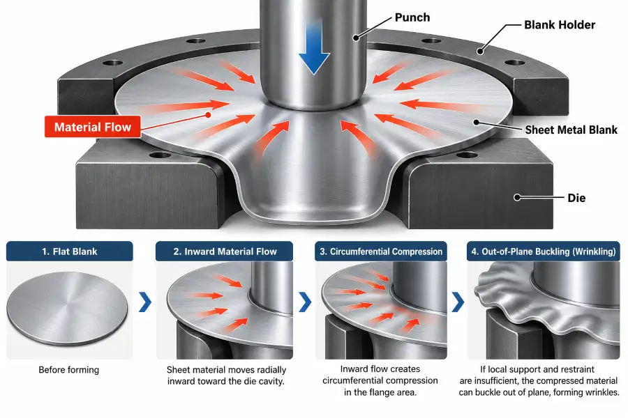
Sheet metal forming relies on controlled plastic deformation. When a punch pushes sheet material into a die cavity, different zones of the blank experience distinct stress states. While some areas are drawn under tension, other areas—particularly material moving inward from the outer perimeter—are forced into smaller circumferences.
This circumferential movement generates compressive stress within the plane of the sheet. Sheet metal can sustain tensile deformation during forming, while its resistance to out-of-plane buckling under compression depends strongly on local stiffness and support conditions. When internal compressive stress exceeds the local buckling threshold of an unsupported area, the metal can relieve that stress by buckling out of plane, creating waves or folds known as wrinkles.
In practical terms, wrinkling is an out-of-plane instability that develops when compressive material flow is not adequately supported or restrained. If material flow is not sufficiently restrained or supported by surrounding tooling surfaces, the sheet may take the path of least resistance and buckle.
Flange Wrinkling vs. Wall Wrinkling
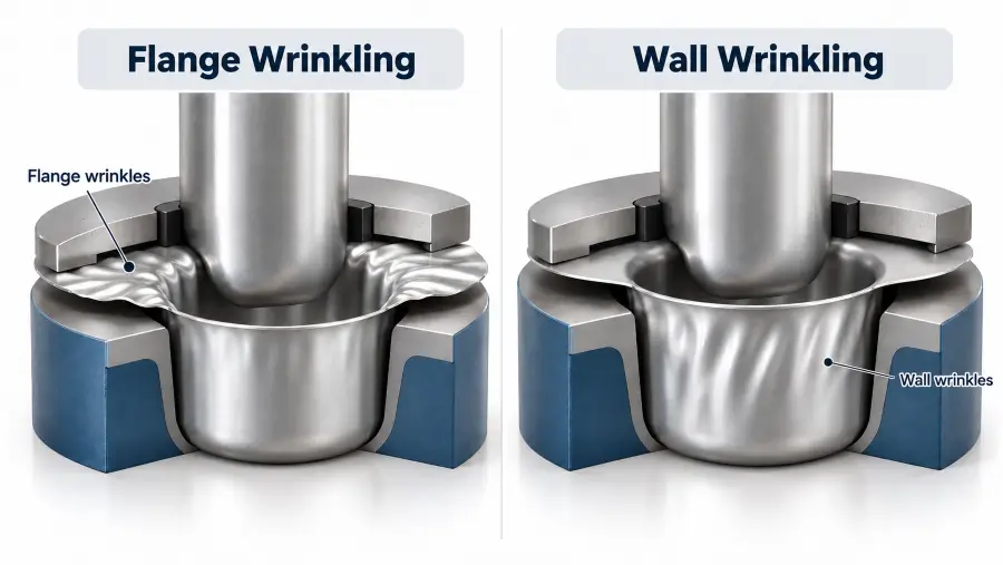
To diagnose wrinkling accurately, tooling engineers classify the defect by where and how it forms during the press stroke. The two most common classifications in drawn and formed parts are flange wrinkling and wall wrinkling:
- Flange Wrinkling: Occurs in the outer perimeter or binder clamping area of the blank. As material is drawn radially inward toward the die cavity opening, its circumference decreases, generating compressive stress under the blank holder. If binder restraint is insufficient or uneven, the material can lift off the tool face and form radial waves.
- Wall Wrinkling: Occurs along the vertical or sloped side walls of a drawn part after the material has left the binder clamping zone and passed over the die entrance radius. Wall wrinkles can develop in unsupported spans between the punch nose and the die shoulder, or where excess material accumulates as it flows into complex cup or box geometries.
Understanding the distinction between flange wrinkling and wall wrinkling is critical because corrective actions that address a flange wrinkle (such as increasing blank-holder restraint) may not resolve—and can sometimes worsen—a wall wrinkle.
Wrinkling Is Different From Springback and Tearing
When troubleshooting formed parts, it is important to distinguish wrinkling from other common metal stamping defects:
- Metal stamping springback refers to the elastic recovery of the material after the forming load is removed, leading to dimensional shape distortion or sidewall curl. While springback is an elastic recovery phenomenon after unloading, wrinkling is an out-of-plane buckling condition that develops during forming.
- Tearing (or Cracking) represents tensile failure that occurs when material stretching exceeds ductility limits.
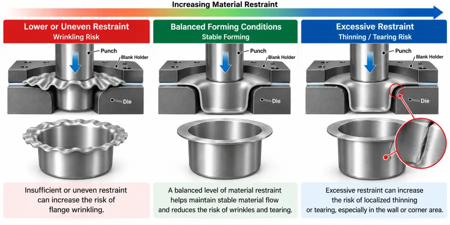
Wrinkling and tearing can reflect different sides of the material-flow and restraint balance. Insufficient or uneven restraint can increase wrinkling risk, while excessive restraint can restrict material flow and increase the risk of localized thinning or tearing.
Main Causes of Sheet Metal Wrinkling
Wrinkling is rarely caused by a single isolated variable. Instead, it typically results from a combination of tooling geometry, process setup, and material conditions that allow unconstrained compressive movement.
Insufficient or Uneven Blank Restraint
The primary mechanism used to manage material flow in drawn parts is the blank holder (or binder). The blank holder clamps the outer margin of the sheet against the die face while the punch draws material into the cavity.
If overall blank-holder restraint is low, compressive stresses may overcome the clamping force, allowing the material to buckle under the binder. Similarly, if the binder face has uneven contact or varied local pressure, sheet metal will naturally flow through lower-restraint areas, potentially leading to localized material gathering.
Excess or Uneven Material Flow
For smooth forming, sheet metal must flow into the die cavity at a controlled rate. If an oversized blank is used, or if certain areas of the blank permit unrestricted material draw-in, more material may enter the die cavity than the geometry can accommodate. This excess material can accumulate inside the cavity, resulting in material crowding and out-of-plane wall wrinkles.
Material Thickness and Sheet Stiffness
Thinner sheet may have lower resistance to out-of-plane buckling under some forming conditions, particularly where unsupported spans are large or restraint is limited. However, thickness alone does not determine wrinkling risk, and thicker drawn parts can also require careful wrinkle control.
Material thickness works together with geometry and restraint. While thinner sheets may require tighter process control, thicker materials can also experience wrinkling if formed into complex geometries with large unsupported areas or insufficient flow control.
Tooling Geometry and Unsupported Sheet Areas
Broader metal stamping design guidelines help frame how tooling geometry supports sheet metal as it transitions from a flat blank into a three-dimensional component. Key geometric factors affecting wrinkling risk include:
- Larger Die Entrance Radii: Larger die entry radii can increase the unsupported sheet span in some forming geometries, which may increase susceptibility to wall wrinkling if material flow and restraint are not well balanced.
- Large Unformed Spans: Shallow angles or broad sloped walls can present areas where the punch does not immediately contact and stretch the sheet, leaving the metal more susceptible to buckling under compressive stress.
Draw-Bead Restraint
When increasing overall blank-holder pressure is insufficient or restricted by press limits, tooling designers can use draw beads. Draw beads are raised features on the binder face that mate with corresponding grooves in the die ring.
Draw beads can provide localized flow resistance and may help control excessive draw-in in appropriate tooling designs. As sheet material moves over a draw bead, the bending and unbending action can increase local flow resistance and back-tension, helping control material draw-in where appropriate.
Friction and Lubrication Conditions
Friction and lubrication conditions can change material flow and local restraint. Depending on the material, tooling geometry, and forming conditions, inconsistent or unsuitable lubrication may contribute to uneven draw-in and wrinkle formation:
- Lubricant Consistency: Excessive or unevenly applied lubricant across the binder face can reduce friction locally, allowing material to move into the die cavity faster in some areas than intended.
- Non-Uniform Application: Dry areas on one portion of a blank combined with heavily lubricated areas elsewhere can create asymmetrical flow resistance, directing material toward lower-friction zones and potentially creating localized wrinkles.
Where Wrinkles Appear Can Help Narrow the Cause
Because a wrinkle’s location reflects where compressive instability overcame local support or restraint, inspecting the part layout provides key diagnostic clues.
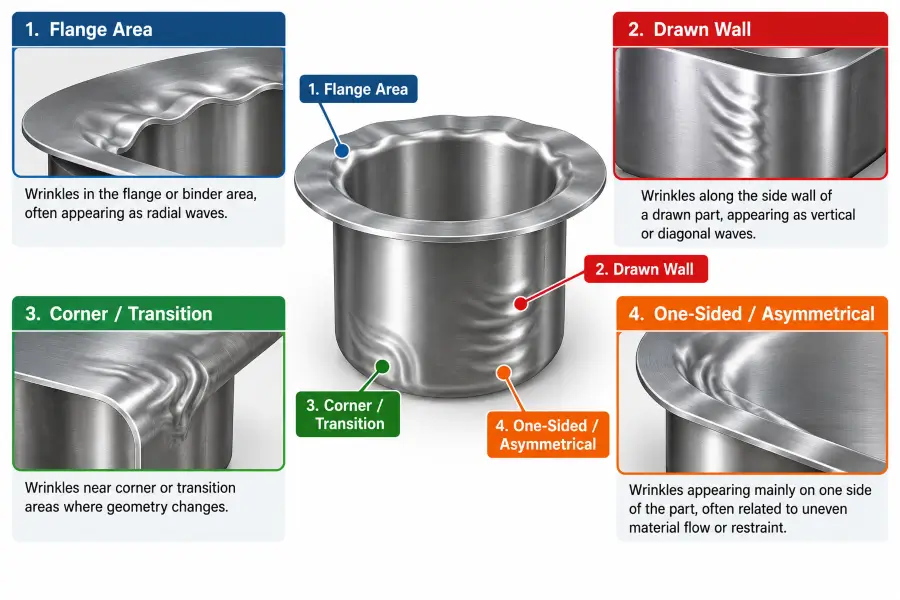
Wrinkles in the Flange Area
Flange wrinkles appear as radial waves or ridges across the metal resting under the blank holder.
- Possible Contributors: Insufficient overall binder restraint, uneven binder contact, or blank sizing that allows the material edge to move out of the clamping zone prematurely during the stroke.
Wrinkles in the Drawn Wall
Wall wrinkles develop along the vertical or angled sides of a formed part. They can take the form of tight vertical folds or broad diagonal waves.
- Possible Contributors: Unsupported sheet spans across large die entry radii, trapped flange wrinkles drawn into the cavity, or uneven material flow entering the wall area.
Wrinkles Near Corners or Geometry Transitions
In box-shaped or complex cup draws, material flowing into corner radii experiences three-dimensional compression from adjacent walls. This gathering effect can create localized corner wrinkles.
- Possible Contributors: Local material crowding, blank geometry with excess material in corner areas, or uneven restraint between straight walls and corner transitions.
Wrinkles That Appear Only on One Side
One-sided wrinkles may indicate uneven material flow, uneven restraint, setup variation, tooling contact differences, or lubrication asymmetry.
- Possible Contributors: Asymmetrical lubrication distribution, setup consistency variations, tooling contact differences across the die, or variations in raw material stock across the sheet width.
Wrinkling During Deep Drawing
Deep drawing operations—where the depth of the part is significant relative to its cross-sectional dimensions—require careful control of material displacement to manage compressive instability.
Circumferential Compression in the Flange
During deep drawing, a flat blank is pulled into a die cavity. As the outer perimeter of the blank moves toward smaller diameters, the material undergoes circumferential compression. Peer-reviewed research on flange wrinkling in deep drawing provides additional engineering background on this instability.
Without adequate blank-holder restraint, this compression can cause the outer flange to buckle into wave patterns. Once formed, flange waves can be pulled over the die entry radius and may become trapped as wall wrinkles or interfere with smooth material flow through the tooling.
How Blank Holding Affects Material Draw-In
The blank holder acts to keep the sheet flat while it undergoes circumferential movement. AHSS Insights provides additional background on binder force control in sheet metal forming. By clamping the flange area, the binder limits out-of-plane buckling and helps direct material movement into uniform radial draw.
If binder restraint is set too low for a given setup, flange wrinkling can begin early in the draw stroke. Maintaining uniform contact and appropriate restraint forces throughout the stroke helps stabilize the blank perimeter.
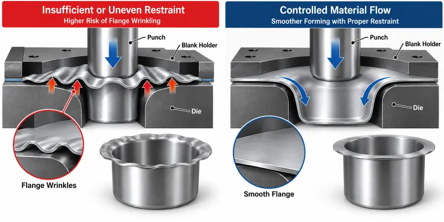
How Draw Beads Change Material Restraint
In deep or complex drawing dies, increasing blank-holder pressure across the entire binder face can be limited by press capacity or increase the risk of thinning elsewhere on the part.
Draw beads address this by applying localized restraint. By forcing material through a curved path, draw beads generate back-tension directly in the entering sheet. This tension counteracts compressive tendencies, helping keep drawn walls smooth without requiring excessive overall clamping force.
The Wrinkling–Tearing Process Window
Successful deep drawing involves managing process variables within a practical operating window:
- Lower Restraint Limit: Insufficient or uneven restraint can increase wrinkling risk due to unconstrained compressive movement.
- Upper Restraint Limit: Excessive restraint can restrict material flow and increase the risk of localized thinning or tearing.
Process setup involves adjusting restraint, geometry, and lubrication parameters so material flows predictably without crossing into either failure condition.
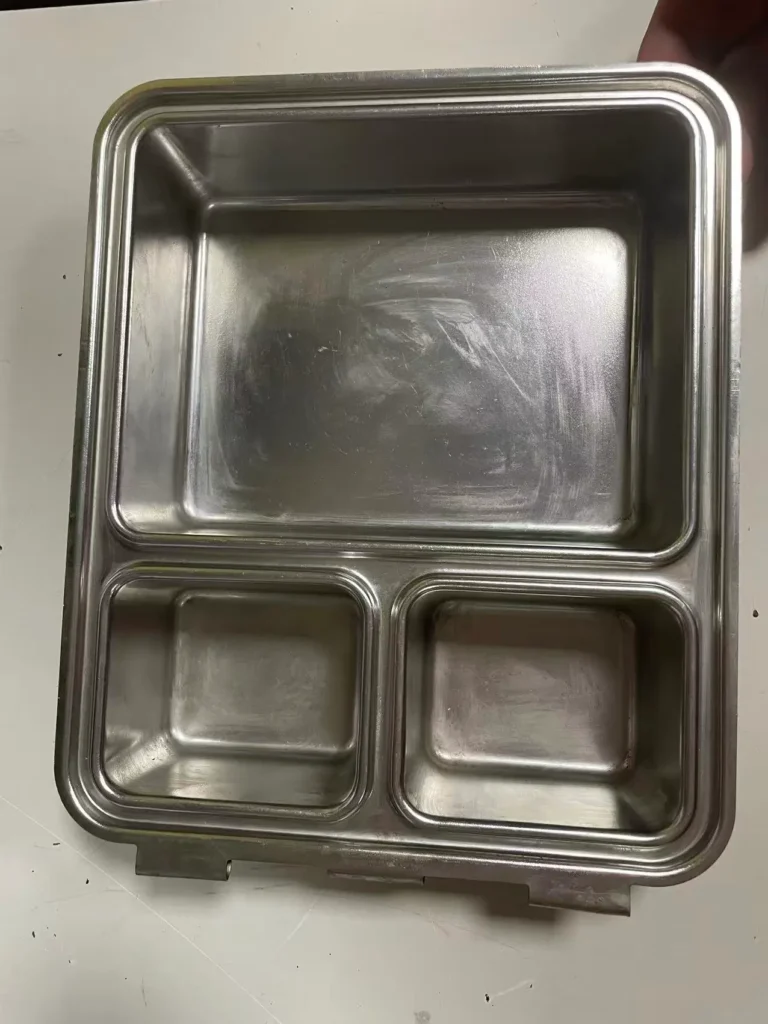
Real Production Perspective: Thin 304 Stainless Steel Tray
Wrinkle Control Can Be Sensitive to Tooling and Setup
In one Metal Stamp Factory project, a relatively thin 304 stainless steel tray required drawing during forming. Because the sheet was relatively thin and the geometry required controlled material flow, the process was sensitive to tooling design and operating conditions.
In this type of part, inadequate control of material flow can increase the risk of wrinkling during forming. Tool design and the experience of the technicians setting up and operating the die therefore played an important role in achieving a stable result.
This example does not mean that 304 stainless steel inherently wrinkles easily. It shows that material thickness, tooling design, material flow, restraint, and process setup need to be considered together.
How to Troubleshoot Wrinkling
When wrinkles appear during production, press personnel should follow a systematic diagnostic process to review process variables before modifying die tooling.
| Observed Pattern | Possible Contributors | What to Review |
|---|---|---|
| Flange Wrinkles | Insufficient or uneven restraint; excess draw-in; material condition | Binder contact; material draw-in behavior; restraint consistency |
| Wall Wrinkles | Trapped flange wrinkles; unsupported sheet span; uneven material flow | Wrinkle origin; die entry geometry; flow balance |
| Corner / Transition Wrinkles | Local material crowding; geometry transition; uneven restraint | Corner material flow; local tooling contact; blank geometry |
| One-Sided Wrinkles | Uneven material flow; uneven restraint; setup or lubrication asymmetry | Tooling contact; setup consistency; lubrication distribution |
| Wrinkles After Setup Change | Changed restraint; lubrication; tooling contact; material condition | Recent setup adjustments; tooling changes; material changes |
| Intermittent Wrinkles | Process variation; material variation; inconsistent lubrication | Run-to-run consistency; material condition; lubrication consistency |
Real Production Perspective: Heavy-Truck Bearing Housing
Wrinkling Is Not Only a Thin-Sheet Problem
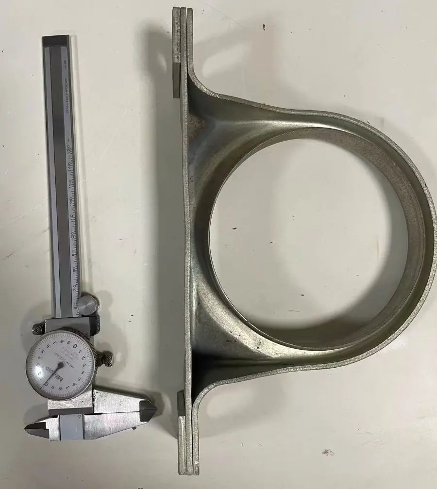
In another Metal Stamp Factory project, a heavy-truck bearing housing was produced from relatively thick steel material through drawing and stamping at our factory. Subsequent projection welding, zinc plating, and plastic overmolding were completed through qualified external partner facilities.
Although the material was thicker than in the stainless steel tray example, wrinkle control was still important during drawing. The part required controlled material flow during forming, showing that wrinkling is not limited to thin sheet.
This case illustrates that material thickness changes forming behavior, but geometry, restraint, tooling, and process setup still need to be considered together.
How to Prevent Wrinkling in Sheet Metal Stamping
Preventing sheet metal wrinkling involves managing material flow during tool design and maintaining consistent control during production setups.
Control Material Flow
Keep material movement into the die cavity smooth and predictable. Review blank shape and sizing to ensure material is not excessive in areas prone to gathering, such as tight corners or deep transitions.
Balance Blank Restraint
Maintain consistent blank-holder contact and restraint across the binder face throughout the forming stroke. Verify that binder surfaces make uniform contact and that restraint mechanisms supply consistent pressure.
Review Draw-Bead Conditions Where Applicable
When draw beads are present, inspect them periodically for wear, scoring, or damage. Ensure draw-bead geometry and engagement provide the intended flow resistance across production runs.
Review Tool Radii and Unsupported Areas
Evaluate die entrance radii and punch radii to ensure they provide adequate support during forming. Radii should allow necessary material flow without leaving large unsupported sheet spans where buckling can initiate.
Maintain Consistent Lubrication and Contact Conditions
Standardize lubrication methods to ensure uniform coverage across production lots. Consistent lubricant application helps prevent localized friction variations that lead to uneven material draw-in.
Review Material Condition
Review material consistency across production lots, including sheet thickness, surface condition, and available material documentation.
Verify Setup Before Permanent Tool Modification
Before grinding, welding, or re-machining die components, perform a systematic process review. Check setup conditions, binder contact, material consistency, and lubrication first. Permanent tooling modifications should only be made after process-level variables have been evaluated.
What OEM Buyers Should Ask When Stamped Parts Start Wrinkling
When evaluating wrinkling concerns on formed components, OEM buyers and quality personnel can use these questions to guide discussions with suppliers:
- Where does the wrinkle first appear?
Purpose: Helps establish whether the defect originates in the binder flange or within the die cavity wall, guiding where to look for potential contributors. - Is it located in the flange or drawn wall?
Purpose: Focuses attention on the relevant zone, ensuring binder restraint concerns are distinguished from cavity geometry or unsupported span considerations. - Does it appear consistently in the same location?
Purpose: Helps determine whether the condition is tied to fixed tooling geometry or variable process conditions like lubrication consistency. - Did the problem begin after a material batch change?
Purpose: Identifies whether variations in raw material thickness, surface condition, or material properties coincided with the issue. - Did it begin after a tooling or setup adjustment?
Purpose: Highlights whether recent setup changes, tool settings, or maintenance activities altered restraint or contact conditions. - Has lubrication or material-flow behavior changed?
Purpose: Evaluates whether changes in lubricant application, viscosity, or coverage affected friction across the binder surface. - How was the corrective action verified before production resumed?
Purpose: Confirms that appropriate metal stamping quality inspection steps—such as evaluating sample parts and inspecting contact conditions—were completed prior to resuming production.
Frequently Asked Questions
1. What causes wrinkling in sheet metal stamping?
Wrinkling is caused by localized compressive instability (buckling) in sheet metal during forming. When internal compressive stresses exceed the material’s resistance to out-of-plane bending, the sheet can fold or wave. Contributing factors include insufficient or uneven blank-holder restraint, excessive unsupported sheet spans, improper material flow, unsuitable lubrication, and material thickness or geometry conditions.
2. Why does sheet metal wrinkle during deep drawing?
During deep drawing, material pulled into a smaller cavity undergoes circumferential compression as its perimeter shrinks. If blank-holder restraint does not adequately support the flange area, or if material flow into the die is unrestricted, this compression can cause the metal to buckle into radial flange waves or wall wrinkles.
3. What is the difference between flange wrinkling and wall wrinkling?
Flange wrinkling occurs under the blank-holder face as material is drawn inward, appearing as radial waves across the flat flange perimeter. Wall wrinkling develops along the vertical or sloped sidewalls of the drawn part inside the die cavity, occurring in unsupported sheet spans or where excess material gathers during forming.
4. Can increasing blank-holder restraint reduce wrinkling?
Increasing blank-holder restraint can reduce flange wrinkling in some forming conditions by limiting excessive draw-in. However, excessive restraint can restrict material flow and increase the risk of thinning or tearing, so the adjustment must be evaluated together with material, geometry, tooling, and lubrication conditions.
5. How can wrinkling be prevented in sheet metal stamping?
Preventing wrinkling involves managing material flow and support throughout the press stroke. Key approaches include optimizing blank-holder contact and restraint, using draw beads where appropriate, sizing tooling radii to minimize unsupported spans, maintaining consistent lubrication, and verifying process setup before modifying die surfaces.
About Metal Stamp Factory
Metal Stamp Factory was established in 2014 in Xiamen, China, focusing on custom metal stamping, tooling development, and precision hardware manufacturing for OEM projects.
When reviewing wrinkling or forming issues, our approach is to compare material condition, part geometry, tooling condition, material flow, restraint, lubrication, and process setup before deciding on corrective action.