A battery cover plate that warps under thermal cycling, corrodes at the mounting points, or fails dimensional tolerance at assembly is a production line problem — not just a parts quality problem. For EV and industrial battery manufacturers sourcing stamped enclosure components, the cover plate is often the last part specified and the first to cause assembly rejection. Here’s how our lithium battery cover plate stamping process avoids exactly that.
Material Selection: Why Q235 Steel with Powder Coat
This battery cover plate is produced from Q235 cold rolled steel (equivalent to SPCC), with black sand texture powder coat applied after stamping. This material and finish combination is chosen for several practical reasons:
Q235/SPCC cold rolled steel offers consistent thickness tolerance, good formability for the complex geometry this cover plate requires, and reliable weldability for any secondary assembly operations.
Black sand texture powder coat provides corrosion protection, eliminates surface reflectivity in enclosed battery installations, and gives the tactile grip needed during maintenance access — when technicians need to remove and reinstall the cover plate in confined spaces.
The sand texture finish also conceals minor surface variations inherent in deep-draw stamping, maintaining consistent visual appearance across the full production batch.
Part Geometry: What Makes This Cover Plate Complex
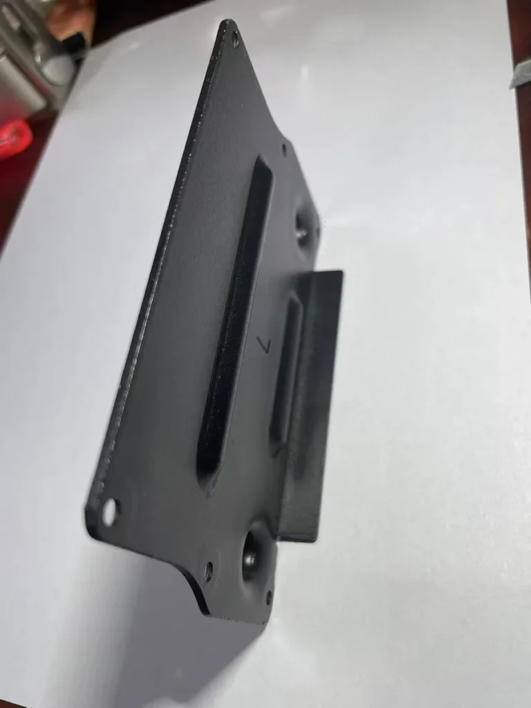
Side profile view — the cover plate has a recessed tray geometry with mounting flanges on all four sides
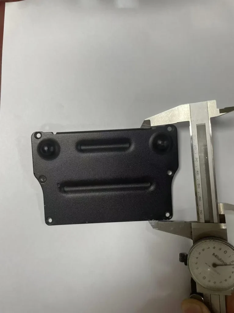
Looking at the part geometry from the side, the cover plate is not a flat panel — it is a shallow tray form with:
A recessed central panel that sits below the mounting flange plane, creating an enclosed cavity when installed
Four corner mounting holes at precise spacing for bolt-down installation
Two elongated slot features on the panel face — these are not decorative, they serve as pressure-relief or ventilation channels depending on the battery pack design
Two dome-shaped raised features on the upper panel surface — these are locating bosses that interface with mating components in the battery pack assembly
Each of these features must be held to dimensional tolerance simultaneously. A die design that holds the slot positions correctly but allows the boss height to vary will cause assembly interference at the customer’s production line.
Left and Right Variants: Why the “L” Marking Matters
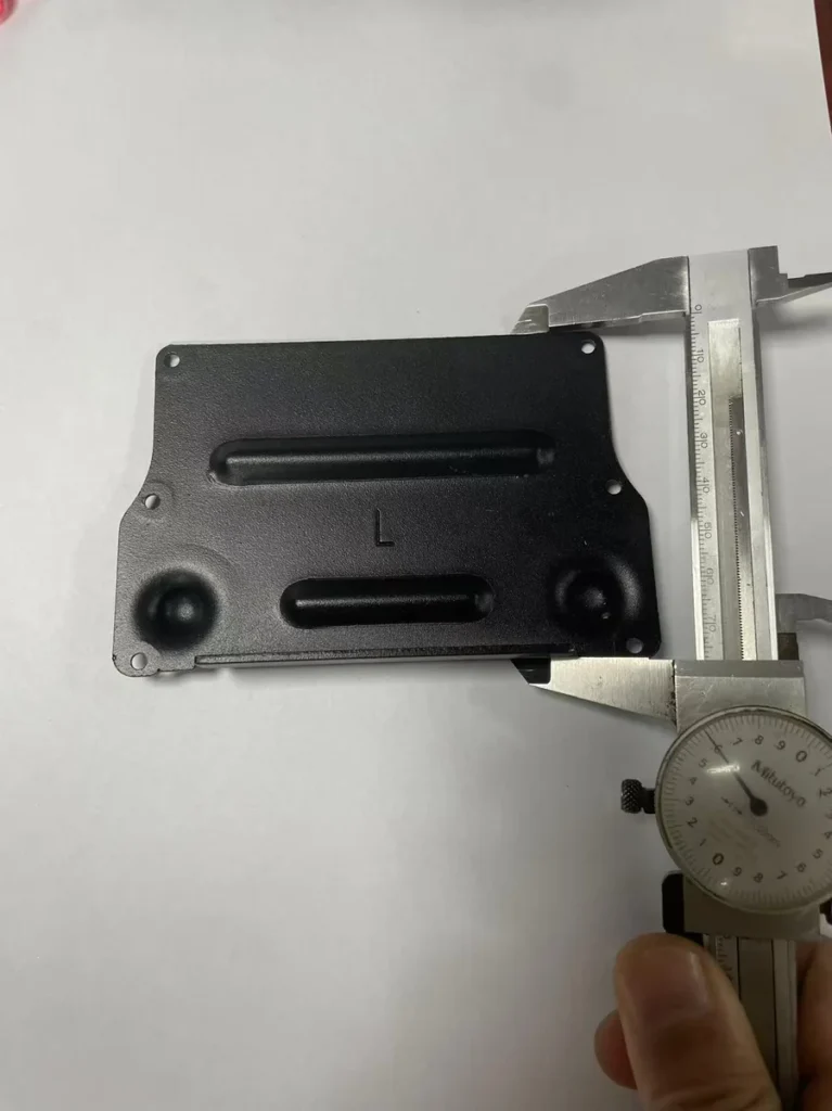
“L” marking indicates the left-hand variant — mirror image right-hand part produced from the same tooling family
The “L” marking stamped into the panel surface indicates this is the left-hand variant of the cover plate. A mirror- image right-hand variant (marked “R”) is produced from a separate die in the same tooling family.
This left/right identification system matters for several reasons at the customer’s assembly stage:
Parts look nearly identical at a glance — without clear marking, line workers frequently install the wrong variant, causing fitment failures that are only discovered at final assembly inspection
The marking is stamped directly into the metal surface during the forming operation — it cannot wear off, peel, or be confused with a separate label that could be applied to the wrong part
For battery pack manufacturers running high-volume assembly lines, clear part identification at the component level is a non-negotiable quality requirement
What Battery Manufacturers Should Specify Before Ordering
Battery cover plates have tighter downstream consequences than most stamped components — a dimensional failure affects not just the cover plate but the entire battery pack assembly it interfaces with. Before placing a production order, confirm these specifications with your supplier:
Boss height and diameter tolerance — these locating features must interface precisely with mating components; a ±0.2mm variation that would be acceptable on a structural bracket may cause interference fit failure on a battery locating boss
Slot position relative to mounting holes — this determines whether ventilation channels align with the battery pack housing cutouts; verify with a sample before mass production
Powder coat thickness range — typically 60–80 microns for this application; too thin reduces corrosion protection, too thick affects fit dimensions at mounting interfaces
Left/right confirmation in writing — confirm which variant and in what ratio before tooling begins, as separate dies are required for each hand
Send us your drawing or sample. We will review the geometry, confirm material and finish options, and provide a free DFM review before quoting. Left/right variants, custom marking, and alternative surface treatments are all available.