Metal Stamping Quality Inspection — Quick Answer
A complete metal stamping quality inspection plan verifies that physical hardware conforms to all released engineering documentation, contractual standards, and functional criteria prior to final acceptance.
In precision metal stamping, quality verification spans multiple potential production stages depending on the agreed inspection plan:
- Incoming Material: Verification of material identity, temper, nominal coil thickness, and material documentation where specified.
- First Article Inspection (FAI): Initial verification of off-tool samples against applicable released drawing notes and critical characteristics.
- In-Process Inspection: Periodic shop-floor verification of selected risk-sensitive features, form geometry, and edge conditions during production runs.
- Final Inspection: Lot-based sampling or audit verification of required final characteristics, surface finish, packaging, and shipping documentation prior to shipment.
Inspection methods should match specific part characteristics. Dimensions, geometric tolerances, burr direction, sheet flatness, surface finishes, and material specifications each require appropriate verification equipment, defined boundary conditions, and agreed-upon sampling logic.
What Does Quality Inspection Mean for Stamped Parts?
To establish a clear quality framework between an OEM buyer and a metal stamping supplier, three fundamental manufacturing concepts must be distinguished: Inspection, Quality Control, and Acceptance.
Inspection
Inspection is the physical activity of measuring, examining, testing, or gauging one or more characteristics of a stamped component and comparing the results against specified requirements. It is a verification function that yields objective evidence of compliance or nonconforming characteristics.
Quality Control (QC)
Quality Control refers to the operational techniques, process monitoring methods, and corrective actions executed throughout tooling setup and press operations to maintain production stability. Quality control activities use inspection data to adjust die conditions, manage strip feeding, address tool wear, and help ensure that part features remain within specified drawing boundaries.
Acceptance
Acceptance is the formal decision process where an OEM buyer or authorized quality representative determines that a single part, a first-article sample set, or an entire production lot satisfies applicable released engineering drawings, contractual specifications, and quality agreements. Acceptance grants authorization for part progression—whether moving to secondary processing, entering stock, or proceeding to final assembly.
Verification activities must always be anchored to a released engineering document. Quality acceptance relies on evaluating physical hardware against released drawing requirements and other pre-defined, mutually agreed-upon specifications.
When Should Stamped Parts Be Inspected?
Quality verification in precision metal stamping is executed across defined control gates depending on the agreed quality plan and project scope.
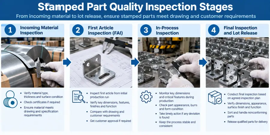
Incoming Material Inspection
Before raw sheet metal coil or strip stock is processed, incoming raw material may be checked. When material verification is required, this step helps confirm raw material identity, nominal strip thickness, and material documentation before raw stock enters active production.
First Article / First-Off Inspection
First Article Inspection (FAI) is performed on initial production samples produced from a new die setup, a reconditioned tool, or an engineering revision change. The primary objective of FAI is to confirm that the setup, strip feeding, and tooling configuration produce parts that meet applicable released drawing requirements before authorizing full production runs.
In-Process Inspection
In-process inspection consists of periodic verification performed on the shop floor during production. Progressive stamping dies undergo wear and thermal shifts over long runs. In-process inspection monitors process-sensitive or wear-sensitive characteristics—such as critical hole sizes, form angles, burr progression, and key features—to detect drift before parts exceed specified limits.
Final Inspection and Lot Release
Final inspection is the quality stage performed after stamping operations and any required secondary processing or surface finishing are complete. This stage uses sample-based auditing or defined checks to verify that finished hardware matches required drawings, packaging specifications, part marking, and required quality records before shipment.
| Inspection Stage | When It Occurs | Typical Checks | Main Purpose |
|---|---|---|---|
| Incoming Material | Upon raw stock receipt prior to processing | Material identity, strip width, nominal thickness, MTR where required | Help prevent nonconforming raw stock from entering production operations. |
| First Article / First-Off | Tool setup, maintenance, or revision change | Applicable drawing features, critical dimensions, form angles, notes | Verify initial setup conformity before authorizing production. |
| In-Process Inspection | Periodic intervals during active press runs | Selected wear-sensitive features, burr progression, bend angles | Detect tool wear and process drift during production. |
| Final Inspection | Post-stamping, secondary finishing, or pre-shipment | Required final dimensions, surface condition, packaging, lot documentation | Confirm finished lot compliance prior to release and dispatch. |
What Characteristics Should Be Inspected on a Stamped Part?
A stamped metal component contains diverse physical, dimensional, and surface attributes resulting from shearing, blanking, piercing, bending, and forming operations. Each characteristic requires an appropriate inspection approach.
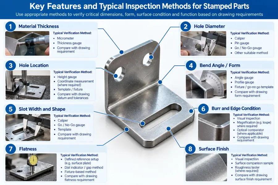
- Material & Thickness: Raw stock alloy identity, temper, and nominal strip thickness verified against purchasing requirements where specified.
- Hole & Slot Geometries: Pierced hole diameters, slot widths, and internal profile shapes subject to punch wear and die clearance.
- Location & Distance Features: Center-to-center hole distances, edge-to-hole offsets, and overall part length or width dimensions.
- Formed Geometry & Bend Angles: Bended tabs, drawn ribs, flanges, and form angles affected by sheet metal springback.
- Geometric Dimensioning & Tolerancing (GD&T): Geometric controls such as hole position, profile of a surface, orientation, and form referenced to drawing datums.
- Burr & Edge Conditions: Punch-exit edge burrs, shearing condition, and edge requirements where specified.
- Flatness & Form: Sheet metal flatness, warping, or bowing across unconstrained or defined restrained mounting conditions.
- Surface Condition & Finish: Cosmetic appearance, absence of heavy die marks or damage, coating presence, and protective finish requirements where specified.
- Critical-to-Quality (CTQ) Characteristics: Designated high-risk features essential for assembly fit, functional performance, or mating interfaces.
- Identification & Traceability: Part revision status, container labeling, lot identification, and packaging protection where required.
| Characteristic | Typical Verification Method | What Is Being Verified | Key Caution |
|---|---|---|---|
| Material Thickness | Blade micrometer or point micrometer | Strip thickness within specification | Avoid measuring directly over edge burrs or formed bend radii. |
| Hole Diameter | Pin gauge (Go/No-Go) or optical comparator | Pierced hole size and profile | Punch wear can cause pierced hole diameters to decrease over time. |
| Hole Center Locations | Optical vision system, projector, or CMM | Center-to-center or datum-to-hole distances | Ensure the part is correctly supported relative to drawing datums. |
| Bend Angles | Protractor, optical comparator, or contour gauge | Form angle compliance | Measure away from corner relief slots and bend transition zones. |
| Burr Height | Optical measurement or depth gauge | Punch-exit edge burr height and direction when limit is specified | Avoid using excessive contact force on flexible edge burrs. |
| Flatness | Suitable reference surface, indicator, or optical method | Deviation from a true flat plane | Verify whether inspection requires free-state or restrained conditions. |
| Plating / Coating | Visual inspection or finish documentation review | Finish presence, coverage, and appearance criteria | Confirm whether drawing dimensions apply before or after finish application. |
| CTQ Features | Suitable gauge, optical system, or checking fixture | Key features critical to assembly or function | Fixture setups should match drawing-defined datum points. |
How Are Stamped-Part Dimensions Inspected?
Dimensional inspection verifies that physical stamped geometry matches the nominal dimensions and specified tolerances on the released engineering drawing. Because sheet metal stampings can be thin or locally flexible, dimensional inspection must consider measurement resolution, feature accessibility, contact pressure, and part support.
Measurement Capability and Resolution
The measuring method should have sufficient resolution and measurement capability relative to the specified tolerance and the required inspection confidence. Small pierced holes, narrow slots, and internal form radii require tools that can access the feature without distorting the metal edge.
Contact vs. Non-Contact Inspection
- Contact Measurement: Tools such as calipers, micrometers, height gauges, and coordinate measuring probes apply physical contact force. When measuring thin-gauge or flexible stampings, excessive contact pressure can flex delicate tabs or affect edge readings. Point or blade micrometers are often preferred over broad flat anvils when measuring local features.
- Non-Contact Measurement: Optical comparators, vision measuring systems, and video measuring instruments project light across the part profile. Non-contact measurement eliminates physical contact deformation, making it suitable for thin-gauge stampings, delicate electrical contacts, and complex 2D profiles.
Datum Setup and Part Support
Dimensional measurements should originate from the drawing’s specified datum structures rather than arbitrary unrefined edges. Stamped components resting on a measurement surface must be supported appropriately so that gravity or part sag does not distort linear distances.
How Should GD&T Requirements Be Verified?
Geometric Dimensioning and Tolerancing (GD&T) defines the allowable variation of geometric features relative to explicit Datum Reference Frames. GD&T verification should reproduce the datum reference frame and feature relationships defined by the drawing in accordance with ASME Y14.5, specifically the 2018 edition reaffirmed in 2024.
The appropriate inspection method depends on the specific geometric control—such as position, profile, orientation, or form—as well as feature accessibility, part rigidity, the datum scheme, and required measurement capability.
For example, when verifying positional controls or profile tolerances relative to a datum reference frame, the inspection setup (whether using coordinate measuring equipment, an optical vision system, or a dedicated checking fixture) aligns the part to the drawing-defined datums before evaluating feature locations. Verifying geometric tolerances directly from unaligned edges without establishing the specified datum framework yields invalid results.
How Are Burr and Edge Requirements Inspected?
Edge shearing in progressive die stamping produces characteristic edge conditions along the cut perimeter. Inspecting burr and edge requirements focuses on verifying edge compliance against drawing callouts rather than analyzing shear mechanics.
Burr Direction and Edge Visual Checks
When drawing callouts define allowable burr requirements (such as “BURR SIDE DOWN”), inspection confirms the burr direction relative to the specified face. Edge conditions are inspected visually or evaluated under appropriate magnification where required by the drawing or quality specification.
Measuring Numerical Burr Limits
When a drawing or quality specification defines an explicit numerical burr height limit, measurement methods appropriate to the requirement are used:
- Non-contact optical systems or optical comparators can measure the burr profile against a calibrated reference without touching the edge.
- Suitable depth indicators or specialized micrometers may be used where contact measurement is appropriate, taking care not to compress the edge structure during measurement.
Burr inspection focuses on confirming whether the burr height and direction comply with released acceptance criteria.
How Are Flatness and Form Requirements Verified?
Flatness or form should be verified under the flatness verification condition defined by the drawing or inspection requirement. For flexible sheet metal parts, support, orientation, free-state condition, or defined restraint can materially affect the measurement result, so the inspection setup must follow the specified acceptance condition.
Free-State Verification
When a drawing specifies flatness in the free-state, the component is evaluated without applying external clamping forces. The part is placed unconstrained on a suitable reference surface, plate, or measurement stage. Flatness may be evaluated using indicator sweeps, optical measurement, coordinate measurement, or gap verification methods appropriate to the specified tolerance and part size.
Restrained Condition Verification
Many flexible sheet metal stampings, contacts, or brackets are designed to be fastened flat during final assembly. Drawings for non-rigid components may specify a restrained condition.
- The part is positioned in a defined checking fixture or holding arrangement that reproduces the assembly mounting points.
- Specified clamping or holding conditions are applied as defined by the drawing or inspection plan.
- Flatness or profile features are then measured while the part is maintained in this restrained state.
Evaluating a non-rigid part in an unconstrained state when the drawing specifies a restrained acceptance condition can lead to false nonconformance findings.
How Should Surface Condition and Finish Be Inspected?
Surface inspection verifies that stamped components meet specified appearance requirements and that secondary treatments comply with defined surface finish requirements.
Surface and Visual Inspection
Visual inspection is conducted under appropriate lighting and viewing conditions defined by the applicable quality standard or customer requirement. Inspectors evaluate stampings for surface conditions such as:
- Tool marks or heavy scoring from press operations.
- Debris or slug marks pressed into the surface.
- Handling scratches, nicks, or tab deformation.
Protective Finishes and Coatings
When stampings receive secondary surface treatments—such as plating, coating, passivation, anodizing, or other specified finishes—checks may include:
- Coverage and Visual Appearance: Confirming complete finish coverage, absence of bare spots, and visual compliance.
- Masking Requirements: Verifying that designated grounding areas, threads, or critical contact zones remained properly masked where specified.
- Dimensional Application: Confirming whether tight feature tolerances apply before or after finish application as defined by the drawing notes.
When specialized coating thickness verification, corrosion testing, or adhesion testing is contractually required, the required test results or documentation should be reviewed against the applicable project requirements.
How Should Material and Traceability Be Verified?
Raw material verification helps ensure that sheet metal stock matches specified alloy grades, tempers, and thickness requirements.
Material Verification and Documentation
When material certification is required by the drawing, purchase order, or quality agreement, incoming material documentation should be checked against the specified grade, condition, and lot or heat identification. This check confirms that material documentation provided with the raw stock aligns with the purchase specification.
Thickness and Condition Checks
Nominal strip thickness is verified using suitable measuring tools such as blade micrometers across the strip. Where specific hardness or temper limits are required by the drawing, material condition checks may be performed where specified in the quality plan.
Traceability Links
Where lot traceability is required, material lot or coil identifiers are linked to press production batches, inspection records, and final shipment documentation. This enables traceability from raw material batch to shipped lot if quality inquiries arise.
A material certificate confirms raw material documentation, but it does not by itself verify every finished-part dimensional or visual characteristic.
First Article Inspection for Metal Stampings
First Article Inspection (FAI) is a quality verification step used to confirm that tooling setups and production processes yield parts meeting released engineering requirements before proceeding with mass production.
Scope and Requirements
The scope, sample quantity, characteristics, and reporting format for first article inspection should follow the customer requirement or agreed inspection plan. Depending on the project, the FAI may cover all applicable released characteristics or a defined subset of inspection-critical features.
An FAI is typically conducted when:
- Producing a custom stamped part for the first time.
- Implementing a formal engineering drawing revision change.
- Re-starting production after major tooling repair, modification, or overhaul.
- Relocating production to a different press line or facility where re-qualification is required.
During FAI, sample parts are measured using appropriate inspection equipment. Measurement results, material documentation where required, and applicable finish records are compiled into a first article report or dimensional inspection record according to the agreed format.
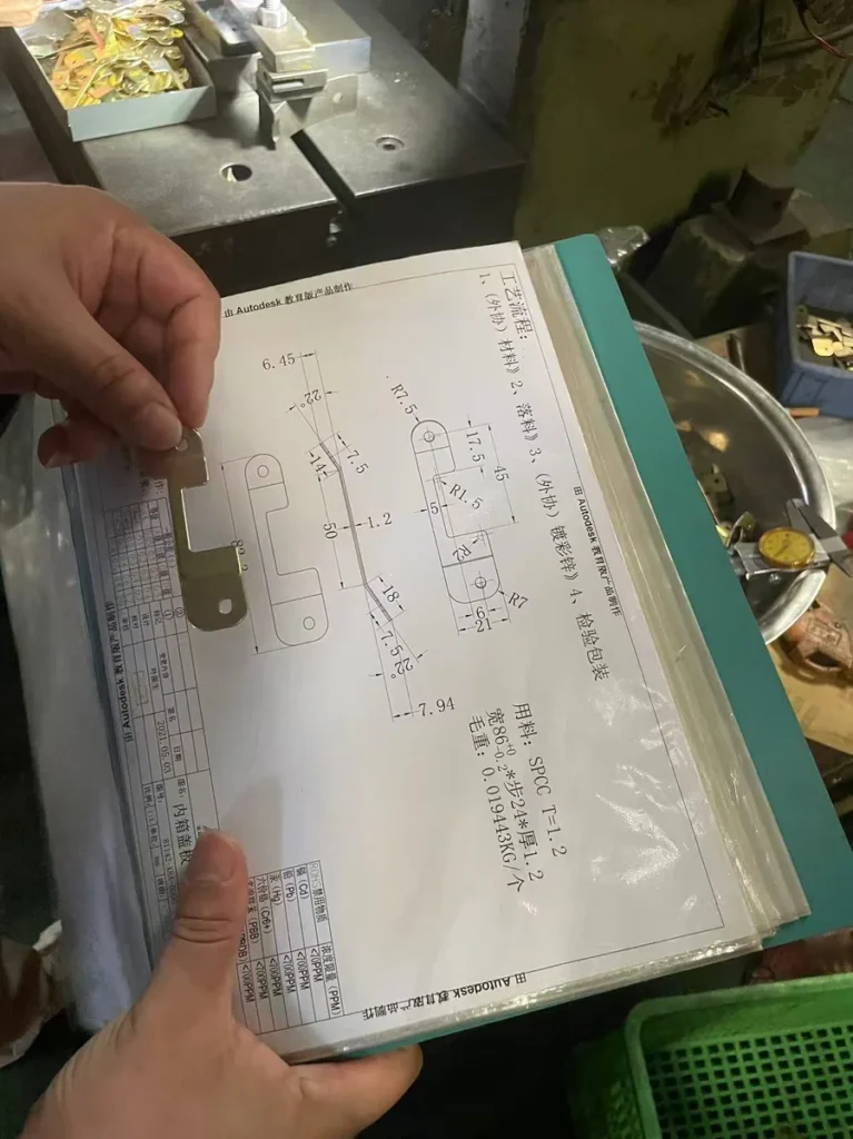
Engineering Note: A conforming first article confirms that the inspected sample or defined first-article set met the applicable released requirements under that inspection condition. It does not, by itself, demonstrate long-term process capability or guarantee that every later production part will conform across extended production runs.
How Should Sampling Inspection and AQL Be Used?
For high-volume metal stamping runs, sample-based lot acceptance sampling is frequently utilized to evaluate lot compliance efficiently.
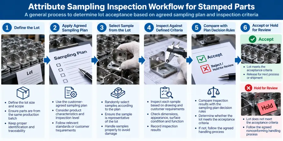
Acceptance Sampling Principles (ISO 2859-1:2026)
Sampling plans for attribute inspection evaluate parts on a pass/fail basis using agreed sampling schemes, including ISO 2859-1:2026 where applicable.
A standard attribute sampling plan establishes:
- Lot Size: The total quantity of stamped components in a production or shipment lot.
- Inspection Level: The relationship between lot size and the selected sample size.
- Sample Size: The number of parts randomly selected from the lot for verification.
- Acceptance / Rejection Criteria: The criteria determining whether the lot is accepted or held for review based on sample results.
Acceptable Quality Limit (AQL) Logic
The Acceptable Quality Limit (AQL) represents a designated quality threshold used in sampling plans. Where defect or characteristic classifications are used, their definitions and associated acceptance rules should come from the customer specification, quality agreement, or agreed sampling plan.
AQL is not a universal metal-stamping defect allowance. The applicable sampling scheme, inspection level, and AQL targets should be explicitly defined in purchase documentation or quality agreements.
Buyer Note: Do not assume that a supplier’s internal sampling practice automatically matches your acceptance requirements. If lot sampling, inspection level, AQL, 100% inspection of selected characteristics, or specific reporting is required, define it in the purchase, quality, or inspection documentation before production release.
Which Inspection Tool Should Be Used?
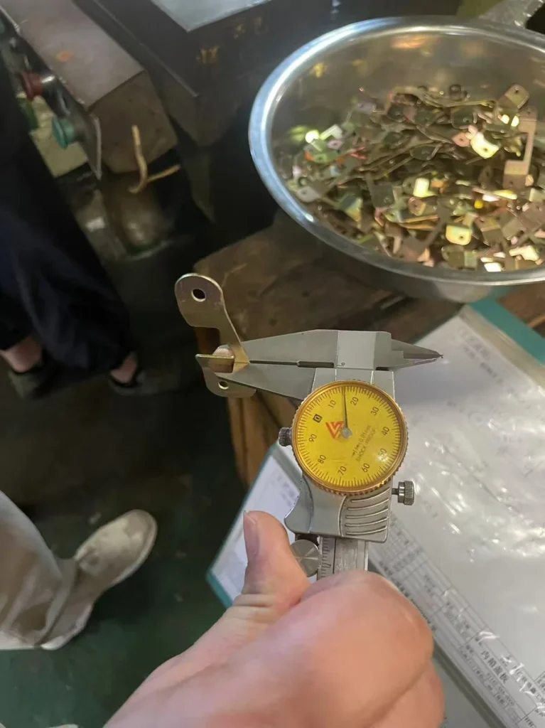
Matching the appropriate measuring device to specific stamped features helps ensure measurement accuracy, avoids part distortion, and supports shop-floor inspection efficiency.
| Tool / Method | Suitable For | Strength | Limitation |
|---|---|---|---|
| Digital Caliper | General linear dimensional checks, outer blank dimensions | Fast and practical for shop-floor measurements | May not be suitable for very tight tolerances, flexible features, or complex geometries. |
| Micrometer (Blade/Point) | Material thickness and external features requiring finer resolution | Good measurement resolution for appropriate local features | Limited geometry access; contact force must be controlled on thin stock. |
| Pin / Plug Gauge | Pierced hole diameters and slot widths | Fast Go/No-Go attribute check for hole boundary limits | Does not provide numerical measurement of true roundness or actual size. |
| Height Gauge & Surface Plate | Vertical linear dimensions, formed tab heights, step offsets | Direct measurement relative to a flat reference surface | Requires stable part positioning and clean reference plate setup. |
| Optical Comparator | Profile shapes, bend angles, edge profiles | Non-contact magnified profile inspection | Limited to 2D silhouette shadow projections and edge profiles. |
| Vision Measuring Machine | Small hole patterns, delicate stampings, complex 2D flat profiles | Fast non-contact optical measurement of flat features | Best suited for 2D profile features; limited vertical 3D measurement reach. |
| Coordinate Measuring Machine (CMM) | Complex 3D forms, GD&T position/profile, spatial features | Accurate 3D spatial measurement referenced to defined datums | Slower measurement speed; touch probe force must be managed on thin tabs. |
Factory Note: For stamped parts, the most sophisticated measuring device is not automatically the best inspection method. Tool selection should follow the feature geometry, tolerance, datum condition, production stage, and required inspection speed. A simple functional gauge or checking fixture may provide a more practical production check than a complex coordinate measurement.
How Should Critical Characteristics and Inspection Frequency Be Defined?
Not all dimensions on an engineering drawing require identical inspection intervals. Inspection frequency should align with characteristic risk and process requirements.
Critical-to-Quality (CTQ) Identification
OEM drawings often designate critical-to-quality characteristics using symbols or explicit callouts. These features usually govern key assembly interfaces, functional mating points, or primary structural locations.
Factors Governing Inspection Frequency
Inspection frequency during press operations may depend on multiple factors:
- Customer Requirements: Contractual quality agreements or explicit drawing instructions.
- CTQ Status & Risk: Higher-risk or CTQ characteristics may justify more frequent verification, depending on customer requirements and the agreed control plan.
- Process Stability & Tooling Condition: Die design, punch wear rates, and historical stability influence how often features require verification.
- Production Stage: Inspection frequency may vary between setup verification, early run monitoring, and routine production.
- Measurement Method: Quick optical or gauge checks can occur frequently, whereas lengthy offline measurements may be scheduled periodically.
- Destructive vs. Non-Destructive Testing: Destructive tests are performed on controlled sample sizes rather than continuous intervals.
What Should Be Included in a Stamped-Part Inspection Report?
An inspection report provides documented evidence that a lot or sample set of stamped parts was verified against released specifications.
| Report Field | Purpose |
|---|---|
| Part Number & Description | Identifies the component name and part number. |
| Drawing Revision Level | Confirms verification matched the active released drawing revision. |
| Lot / Batch Reference | Links inspection results to production batch or raw material lot where required. |
| Sample Size & Identification | States the number of inspected parts and sample identifiers. |
| Characteristic / Feature Index | Maps reported inspection lines to ballooned drawing features or notes. |
| Nominal & Tolerance Limits | Displays specified drawing dimensions and allowable upper/lower limits. |
| Actual Measurement Results | Records physical numerical or attribute values measured for each sample. |
| Inspection Method / Tool | Identifies equipment used (e.g., Pin Gauge, Caliper, Optical System, CMM). |
| Pass / Fail Status | States conformance status for each evaluated characteristic. |
| Inspector Name & Date | Records the inspector and completion date. |
| Deviation Reference (Where Applicable) | Cites approved concession or engineering waiver reference if present. |
What Happens When a Stamped Part Fails Inspection?
When a nonconforming characteristic is detected during incoming, in-process, or final quality verification, a practical reaction framework may include the following steps:
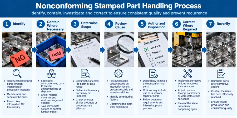
- Identify: Clearly mark or flag the nonconforming characteristic or sample.
- Segregate / Contain: Contain potentially affected material to prevent accidental mixing with accepted inventory.
- Determine Quantity: Identify the scope and quantity of potentially affected parts.
- Review Cause: Investigate the underlying cause, evaluating tooling, setup, material, or process factors.
- Disposition: Determine material disposition through the authorized customer or supplier process (e.g., rework, scrap, or formal customer concession review).
- Correction: Correct the relevant process, tooling, material, or documentation where required.
- Re-Verify: Re-verify applicable characteristics before releasing corrected hardware.
First Article vs. In-Process vs. Final Inspection
| Inspection Type | Primary Purpose | Typical Scope | Timing | Typical Record |
|---|---|---|---|---|
| First Article | Verify initial conformity | Applicable released characteristics | Initial production or defined trigger | FAI / dimensional report where required |
| In-Process | Detect process drift | Selected risk- or process-sensitive characteristics | During production according to defined plan | In-process inspection record |
| Final | Confirm release requirements | Required final characteristics | Before lot / shipment release | Final inspection or release record |
OEM Stamped-Part Quality Inspection Checklist
This checklist helps OEM buyers and quality engineers confirm that inspection and acceptance requirements are defined before production release.
| Requirement | Confirmed? |
|---|---|
| Active 2D engineering drawing revision level explicitly confirmed | ☐ |
| Critical-to-Quality (CTQ) characteristics and key functional dimensions identified | ☐ |
| Material verification / certification requirements defined where applicable | ☐ |
| First Article Inspection scope, sample quantity, and reporting format defined where applicable | ☐ |
| Sampling plan / AQL requirements defined where applicable | ☐ |
| Measurement methods for delicate, flexible, or complex features agreed upon | ☐ |
| Allowable burr direction and burr limits designated on drawing where required | ☐ |
| Flatness verification condition specified (Free-State vs. Defined Restrained Condition) | ☐ |
| Surface finish, plating specifications, and “Before/After Finish” notes clarified | ☐ |
| Material lot traceability and container labeling requirements defined where required | ☐ |
| Required inspection / quality documentation defined where applicable | ☐ |
| Nonconformance communication and concession review contacts established | ☐ |
| Packaging / protection requirements defined where they affect the accepted condition | ☐ |
From Our Stamping Experience: Inspection Starts with Clear Acceptance Requirements
Metal Stamp Factory was established in 2014 in Xiamen, China, focusing on custom metal stamping and precision hardware manufacturing. The founder of Metal Stamp Factory, Shengtong Chen, started learning mold making and metal stamping at the age of 17 and has accumulated more than 25 years of hands-on manufacturing experience in tooling development, metal stamping, and OEM production.
In custom metal stamping manufacturing, practical quality verification depends on more than checking dimensions immediately after the press operation. The accepted condition should reflect the stage at which the customer will actually receive or use the part.
Factory Experience Example: Post-Plating Deformation Found Before Shipment
In one motorcycle-component project involving a stamped steel part, the parts met the required dimensional checks after stamping and were then sent for secondary electroplating. During plating, too many parts were processed in a single batch, and some parts returned with visible shape deformation.
The issue was identified during the final pre-shipment comparison against the released drawing and the approved sample condition. Because the deformation was detected before shipment, the affected parts were reviewed and corrected through an additional single-hit re-forming operation, followed by re-verification before release.
This experience highlights an important inspection principle: conformity after stamping does not automatically guarantee conformity after secondary processing. Plating, coating, heat exposure, bulk handling, or other downstream operations can change the delivered condition of a stamped part. When these processes can influence geometry or appearance, final acceptance should verify the part in its finished condition rather than relying only on pre-finish inspection results.
Effective quality practices therefore rely on four core principles:
- Start with Released Requirements: Inspection must evaluate parts against the active drawing revision and mutually agreed specifications.
- Match Method to Feature: Different characteristics—whether flexible tabs, tight hole matrices, or surface finishes—require verification methods suited to their geometry and material condition.
- Verify After Relevant Secondary Processing: When downstream processing can affect geometry, finish, or function, inspect the finished condition required for delivery.
- Align Expectations: Defining FAI scope, reporting expectations, sampling criteria, and critical features in advance supports straightforward verification and acceptance.
Clear documentation helps protect tooling investments, supports efficient quality verification, and reduces ambiguity about whether delivered components meet their intended requirements.
Frequently Asked Questions About Metal Stamping Quality Inspection
What should be inspected on a stamped metal part?
A stamped-part quality inspection verifies material thickness, pierced hole diameters, hole locations, bend angles, formed profiles, GD&T characteristics, burr direction and height where specified, sheet flatness, surface finish, and CTQ features against released engineering drawings.
What is the difference between first article inspection and final inspection?
First Article Inspection (FAI) verifies that an initial production setup or tool revision yields parts meeting applicable released drawing notes before full production proceeds. Final inspection is a lot-based verification performed on completed hardware to confirm final dimensions, surface finish, packaging, and shipping documentation prior to shipment.
Does every stamped part require 100% inspection?
No. Whether 100% inspection is appropriate depends on the characteristic risk, customer requirement, inspection method, process control strategy, and agreed inspection plan. Whether inspection is sample-based, periodic, or 100% for selected characteristics should be defined according to customer requirements, characteristic risk, process controls, and the agreed inspection plan.
What measuring tools are used for stamped metal parts?
Common measuring tools include digital calipers, blade micrometers, pin/plug gauges, height gauges on reference plates, optical comparators, 2D vision measuring systems, checking fixtures, and coordinate measuring machines (CMM) depending on feature geometry and tolerance requirements.
How should burrs and edge conditions be inspected on stamped parts?
Burrs are verified for specified burr direction, visually inspected for edge condition, and evaluated under magnification or optical comparators where required. When a numerical burr limit is explicitly specified on the drawing, non-contact optical tools or suitable depth gauges measure the burr height against released requirements.
How is flatness checked on a stamped metal part?
Flatness verification depends on drawing specifications. Parts are evaluated relative to a suitable reference surface using indicators, feeler gauges, optical systems, or coordinate measuring equipment. For flexible non-rigid parts, measurement must follow drawing notes specifying whether verification occurs in a free-state or under a defined restrained condition.
What does AQL mean in metal stamping inspection?
AQL stands for Acceptable Quality Limit under attribute sampling standards like ISO 2859-1:2026. It represents a designated quality threshold used in sampling plans. Specific AQL values, defect classifications, and inspection levels must be defined in the agreed customer quality plan.
What should an OEM buyer request in a stamped-part inspection report?
An OEM buyer should request an inspection report mapped to drawing features containing: part number, active drawing revision, lot reference, sample size, nominal dimensions, specified tolerance limits, actual measured values, inspection method used, pass/fail status, and inspector signature or date.
Send Your Stamped Part Requirements for Engineering Review
Preparing a custom metal stamping project or defining quality acceptance criteria for an upcoming production run? Metal Stamp Factory provides engineering reviews of drawings, material specifications, inspection requirements, and production parameters to support your manufacturing needs.
Submit your project documentation for a technical review:
- 2D engineering drawings (PDF / DWG) with active revision levels
- 3D CAD models (STEP / IGES) where available
- Material specifications and temper requirements
- Critical-to-Quality (CTQ) characteristics and tolerance expectations
- Surface finishing or plating requirements where applicable
- Quality documentation and inspection report requirements
- Estimated program quantities and delivery schedules