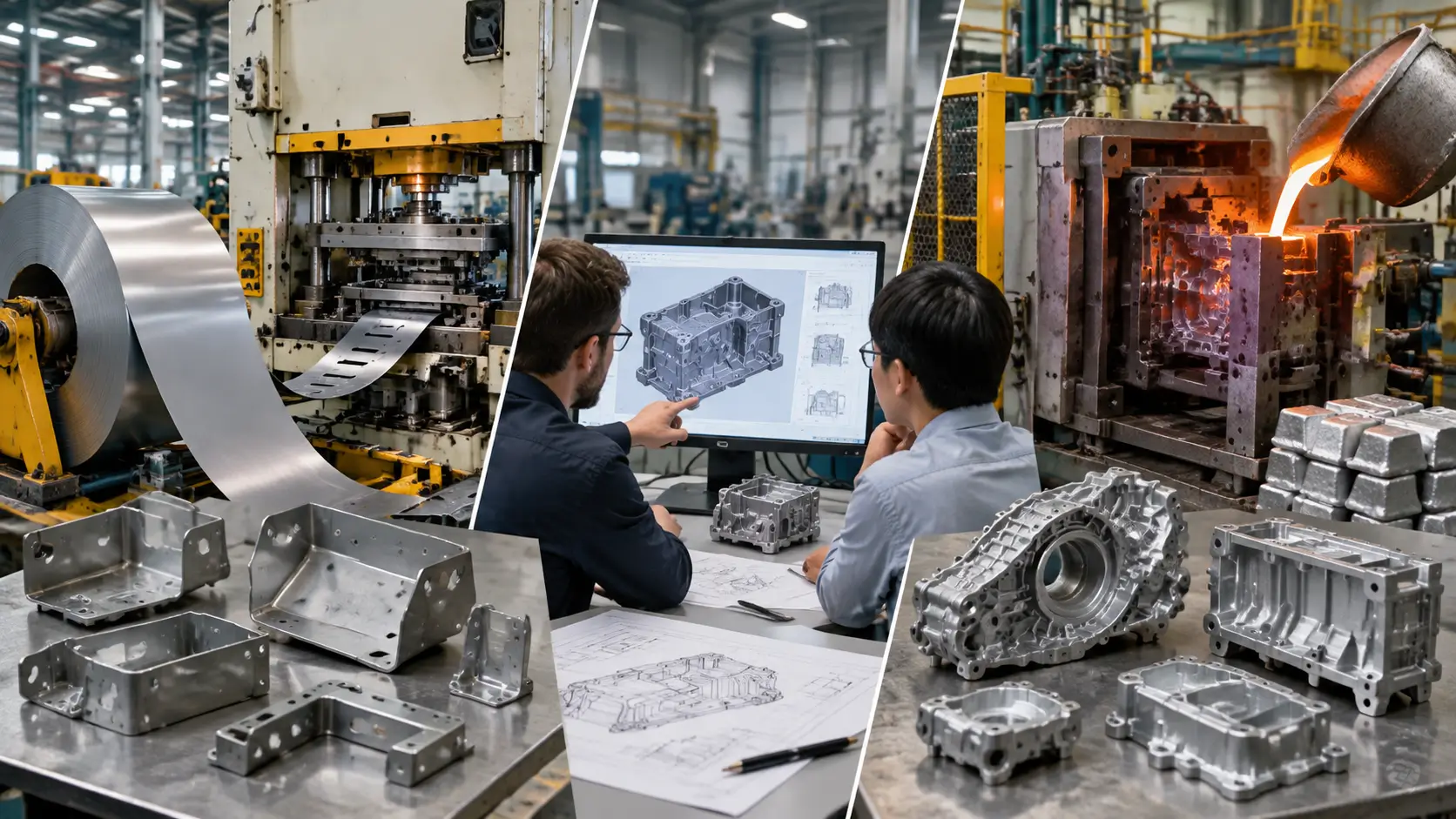
Designing sheet metal components for high-volume manufacturing requires a clear understanding of metal stamping design guidelines. While early-stage CAD models focus primarily on component fit and functional performance, successful production depends on Design for Manufacturability (DFM). DFM bridges the gap between theoretical product design and practical tooling physics, ensuring that parts can be stamped consistently, economically, and without premature tool wear or material failure.
For OEM engineers, product designers, and sourcing managers, applying metal stamping design guidelines early in the development cycle prevents costly tool modifications, reduces scrap rates, and stabilizes high-volume production. This guide details the essential geometric design considerations for stamped metal parts—from pierced holes and formed bends to material grain orientation and progressive die compatibility.
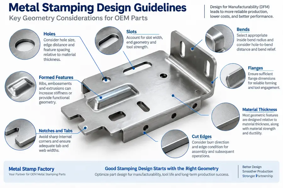
What Is Design for Manufacturability (DFM) in Metal Stamping?
| Design Area | Common Risk | DFM Consideration |
|---|---|---|
| Hole Features | Punch breakage, burrs, distortion | Balance hole size, thickness, clearance, and material strength |
| Bend Features | Cracking, springback, deformation | Control bend radius, grain direction, and relief geometry |
| Feature Spacing | Die steel weakness, web distortion | Maintain adequate spacing between holes and cutouts |
| Formed Features | Material tearing or thinning | Evaluate forming depth, radii, and material ductility |
| Progressive Die Compatibility | Strip instability and feeding issues | Consider carrier design, pitch, and feature sequence |
Design for Manufacturability (DFM) in metal stamping is the practice of designing part geometry so that it aligns with the mechanical behavior of sheet metal and the physical limitations of stamping dies. Unlike general 3D CAD modeling, where any shape can be rendered digitally, physical metal stamping involves high-speed shearing, stretching, compressing, and bending of solid metal strips under immense tonnage.
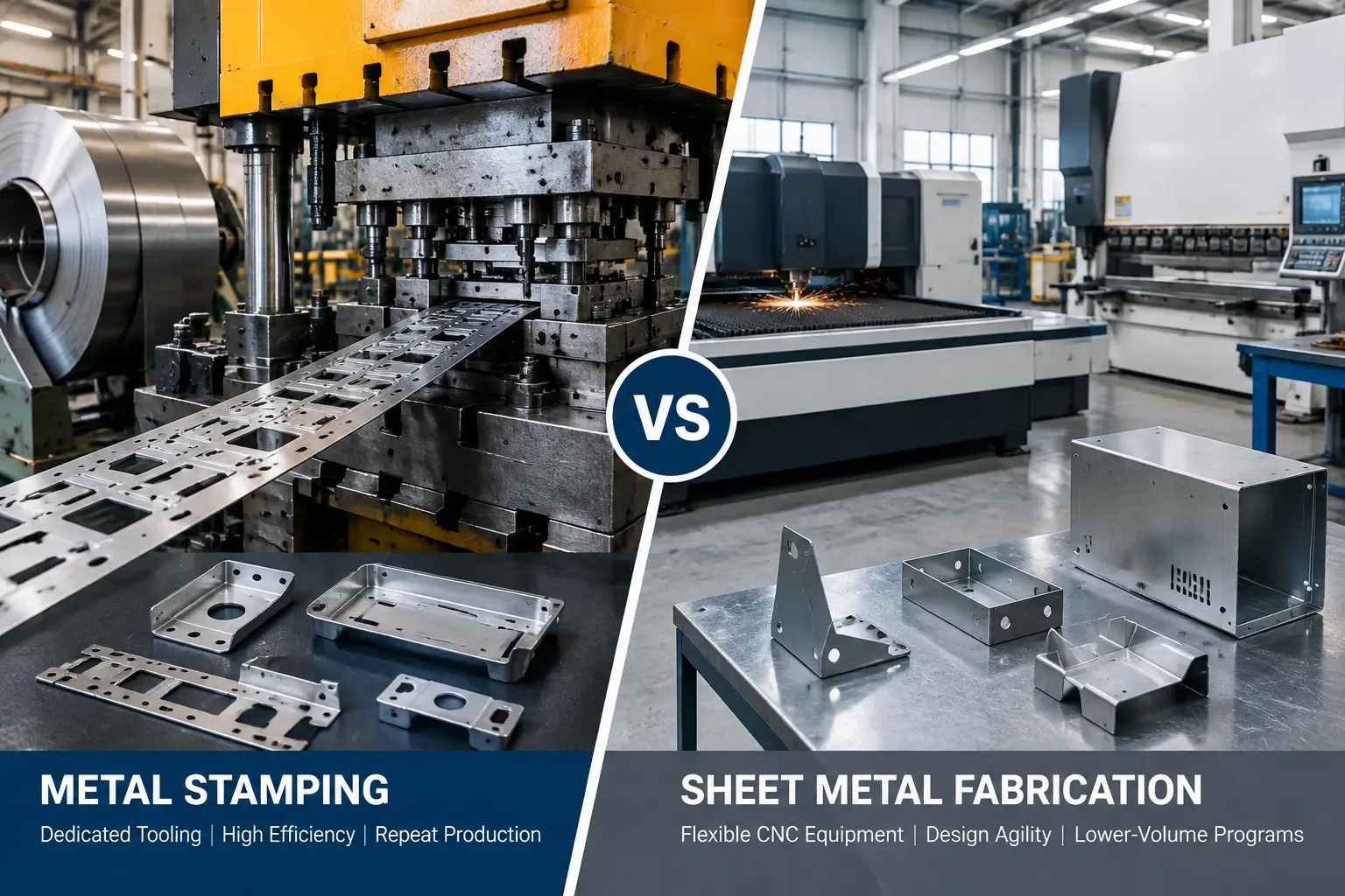
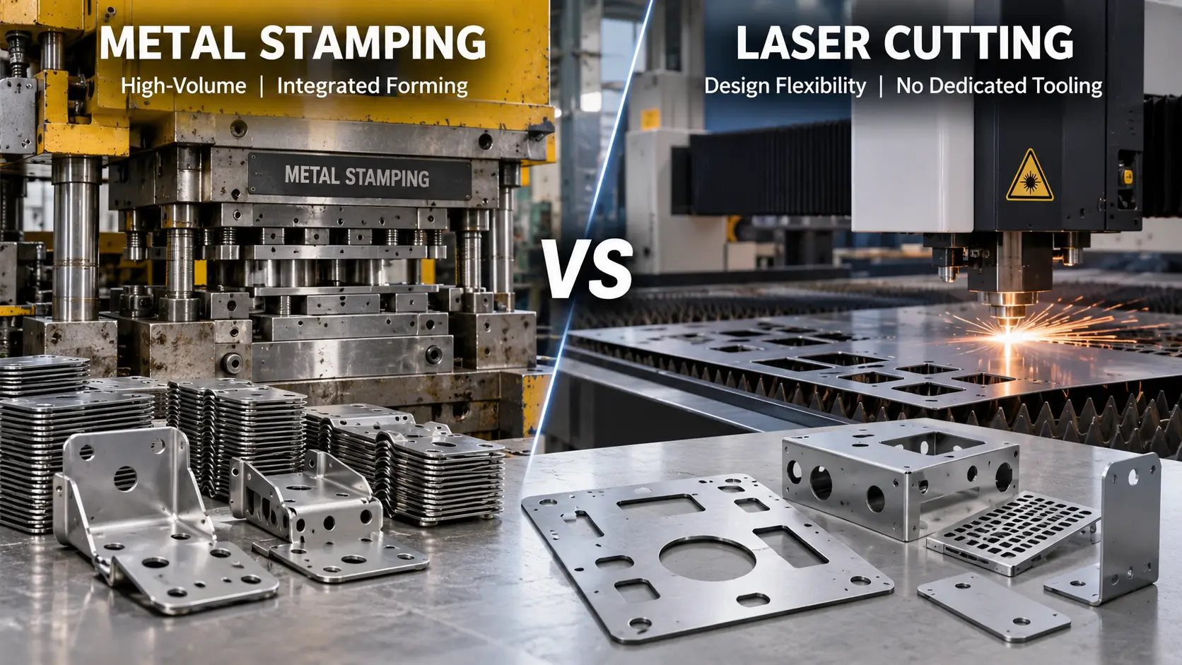
It is critical to distinguish metal stamping DFM from general sheet metal fabrication guidelines. Low-volume sheet metal fabrication relies on equipment such as laser cutters, CNC punch presses, and press brakes. These processes offer high flexibility and accommodate varying edge geometry or tight internal features because tools do not need to enclose the workpiece fully.
Conversely, high-volume metal stamping relies on hard tooling—custom-engineered progressive, compound, or transfer dies running in dedicated presses. Hard tooling subjects small die elements, punch tips, and matrix edges to high cycle counts and severe mechanical fatigue. Consequently, features that are easily laser-cut or bent on a press brake may cause rapid tool breakage, excessive burrs, or strip feeding instability in a stamping press. Executing a dedicated DFM review for hard tooling ensures the geometry supports both part function and tool durability.
Why Material Thickness Is the Foundation of Stamping Geometry
In sheet metal stamping, virtually every geometric feature—including hole diameters, edge distances, bend radii, and relief slots—is evaluated relative to nominal material thickness. Material thickness determines the cross-sectional area being sheared or formed, directly dictating the required tonnage, die clearances, and localized stress levels.
Because force scales with thickness, many design handbooks and preliminary DFM guides express geometric recommendations as proportional ratios of material thickness. Designing features proportional to thickness helps balance structural strength against tool loading.
However, thickness-relative guidelines must be treated as preliminary reference points rather than absolute physical laws. A ratio that performs reliably on low-carbon, annealed steel may fail when applied to high-strength alloys or fully hardened tempers. Material ductility, yield strength, tensile strength, and hardness significantly alter how metal flows under pressure and how much force small punch elements must withstand. OEM engineers should use thickness-based guidelines as an initial design check while relying on formal DFM reviews to validate specific material and temper combinations.
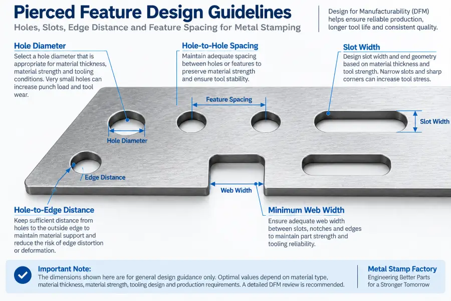
Pierced Feature Design Guidelines
Piercing—the operation of punching holes, slots, or cutouts into flat sheet metal—places intense stress on both the workpiece and the steel punches. Proper feature sizing and placement prevent tool breakage and edge distortion.
Minimum Hole Size
Designing pierced holes too small relative to sheet thickness introduces significant engineering risks. During the piercing stroke, the punch tip experiences intense compressive column loading. If the punch cross-section is too slender compared to the force required to shear through the material thickness, the punch may deflect, buckle, or chip prematurely.
Key factors influencing minimum hole sizing include:
- Punch Structural Strength: Slender punches exhibit high length-to-diameter ratios, making them vulnerable to fatigue and bending.
- Material Tensile and Yield Strength: Higher-strength materials demand greater shearing force, increasing the mechanical load on the punch tip.
- Punch-to-Die Clearance: Insufficient clearance increases punching force and tool wear, while excessive clearance causes heavy burrs and hole distortion.
- Tool Life Expectations: Larger hole diameters reduce stress on tool steel, extending maintenance intervals and overall die life.
Preliminary DFM guides often reference a hole diameter roughly equal to the material thickness as an initial rule of thumb for ductile, low-carbon steels. However, this ratio should not be treated as a universal minimum or a guarantee of tooling capability. For high-strength steels, stainless steels, or hard tempers, larger hole-to-thickness ratios are typically evaluated during DFM to preserve punch integrity. If an application requires a hole diameter smaller than the stock thickness, specialized punch guidance or alternative manufacturing strategies must be reviewed.
Hole-to-Edge Distance
| Feature | Main Concern | DFM Evaluation |
|---|---|---|
| Hole Diameter | Punch strength and tool life | Evaluate thickness ratio and material strength |
| Hole-to-Edge Distance | Edge deformation and cracking | Maintain sufficient supporting material |
| Hole-to-Hole Spacing | Die wall strength | Avoid weak punch and die sections |
| Slot Geometry | Punch deflection | Use proper width-to-length proportions |
Placing a pierced hole too close to the outer edge of a part creates a thin web of material that lacks structural support during the shearing stroke. As the punch enters the metal, lateral forces push outward against the free edge.
If the edge margin is insufficient, several manufacturing issues occur:
- Edge Bulging: The unsupported material deforms outward, causing an out-of-round part perimeter.
- Hole Distortion: The hole itself distorts into an oval or irregular shape as stress releases unevenly toward the nearby edge.
- Punch Deflection: Unequal resistance across the face of the punch causes it to deflect toward the weak edge, accelerating tool wear and die chipping.
Preliminary DFM rules of thumb often recommend maintaining a clearance between the edge of a hole and the outer cut edge of the component that is proportional to material thickness. High-strength materials or critical profile margins require greater distance to ensure the surrounding metal adequately supports the shearing action.
Hole-to-Hole and Feature Spacing
When two pierced features are positioned too close together, the narrow strip of metal separating them is called a web. In a stamping die, this web corresponds to a thin section of die steel between matrix openings or two closely spaced punches.
If feature spacing is inadequate:
- Die Steel Fracture: The thin wall of tool steel in the die cavity is subjected to alternating stress cycles and may fracture under pressure.
- Web Distortion: The sheet metal web between the holes may bulge, twist, or tear during punching.
- Feature Interaction: Shear zones from adjacent punches overlap, creating unpredictable stress concentrations and burr formation.
Preliminary DFM handbooks frequently suggest spacing adjacent holes by a distance multiple of material thickness, with an absolute minimum distance maintained to protect die steel integrity. Complex layouts with dense hole patterns often require staggered punching across multiple progressive die stations to maintain tool strength.
Slots and Narrow Openings
Slots and narrow cutouts function similarly to round holes but present unique punch geometry challenges. Long, narrow slots require blade-like punches that lack structural rigidity across their narrow width.
Key considerations for slot geometry include:
- Punch Aspect Ratio: Extremely long and thin punches are highly susceptible to twisting and side deflection during contact with the stock.
- Slot End Geometry: Sharp rectangular slot ends create severe stress concentrations at the punch corners. Designing rounded ends (full radii or generous corner fillets) significantly improves tool strength and extends die life.
- Narrow Web Sections: The material remaining around a slot must withstand subsequent forming or blanking forces without buckling.
Preliminary guidelines often recommend slot widths proportional to material thickness, paired with generous end radii to distribute cutting forces evenly.
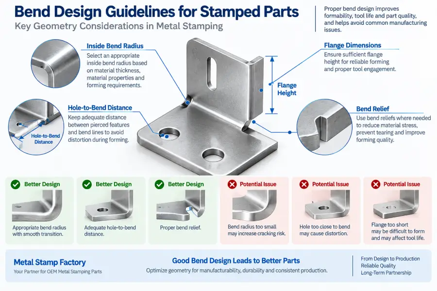
Bend Design Guidelines for Stamped Parts
Bending transforms flat metal strips into three-dimensional shapes. Because bending involves both tension on the outer surface and compression on the inner surface, geometric features around the bend zone must accommodate localized material deformation.
Inside Bend Radius
The inside bend radius is one of the most critical parameters in sheet metal DFM. Forming a sharp, zero-radius bend forces the outer surface of the sheet metal to undergo extreme elongation, while the inner surface compresses tightly against the punch edge.
Applying an excessively tight inside bend radius introduces multiple manufacturing risks:
- Material Cracking: Outer surface fibers stretch beyond the material’s ultimate tensile strength, resulting in surface fracturing or complete material failure along the bend line.
- Tooling Stress: Tight radii concentrate forming forces on a sharp punch tip, leading to rapid tool wear and galling.
- Process Sensitivity: Small variations in material thickness, hardness, or coil batch properties cause inconsistent bend angles and severe springback variation.
The allowable inside bend radius depends directly on material ductility, temper, yield strength, stock thickness, and grain direction. Ductile materials like soft aluminum or annealed low-carbon steel tolerate smaller bend radii relative to thickness. Conversely, high-strength steels, spring tempers, and hard aluminum alloys require substantially larger inside radii to prevent cracking. Designing with generous inside bend radii creates a stable, repeatable forming process and protects tooling investment.
| Bend Factor | Manufacturing Impact |
|---|---|
| Inside Bend Radius | Controls cracking risk and forming stability |
| Grain Direction | Influences fracture tendency during bending |
| Hole-to-Bend Distance | Prevents hole distortion after forming |
| Bend Relief | Reduces tearing and stress concentration |
| Flange Height | Ensures stable tool engagement |
Hole-to-Bend Distance
When a hole or slot is positioned too close to a bend line, it enters the plastic deformation zone created during forming. As the die bends the metal, material within this zone stretches and flows.
If a hole is located within or adjacent to this active forming region:
- Hole Distortion: The round profile of the hole stretches into an oval or teardrop shape.
- Flange Deformation: The presence of the cutout removes structural resistance, causing the bend line to bulge or fracture near the hole.
- Tooling Interference: The hole edge may catch on forming die inserts, causing burrs or part jamming.
Preliminary DFM guidelines typically suggest keeping feature edges clear of the forming zone using preliminary spacing rules based on material thickness and inside bend radius. If part design dictates that a feature must reside near a bend line, OEM engineers should incorporate bend relief slots or plan for feature creation after the bend is formed in the die sequence.
Bend Relief
When a flange is bent locally rather than across the entire width of a sheet metal blank, a high-shear transition occurs between the formed flange and the adjacent flat metal. Without proper geometry at this transition, the metal can tear uncontrollably at the bend corner, resulting in jagged edges and unpredicted stress risers.
Bend reliefs are cutouts or slots placed at the ends of localized bend lines to isolate forming stresses.
Key aspects of effective bend relief design include:
- Relief Width: The cutout is commonly sized wider than the stock thickness to help prevent material binding during the bending stroke.
- Relief Depth: The depth of the relief slot should ideally extend beyond the tangent point where the bend radius meets the flat surface. This helps ensure the deformed zone falls inside the cutout.
- Corner Fillets: Relief slots should incorporate rounded inner corners rather than sharp 90-degree notches to eliminate stress concentrations in the primary blank.
Providing proper bend relief supports clean, predictable flange formation without tearing neighboring material or distorting the flat part profile.
Flange Dimensions
In stamping dies, forming a flange requires the tooling to grip and sweep the metal over a die edge. If a flange is designed too short, the metal strip cannot engage properly with the forming punch and die faces.
Designing extremely short flanges leads to several manufacturability issues:
- Slippage and Instability: The edge of a short flange may slip off the forming radius during press downstroke, resulting in inconsistent bend angles and erratic flange heights.
- Material Distortion: Insufficient leverage forces the material to stretch rather than bend cleanly along the intended axis.
- Tool Wear: High localized friction occurs as the short metal edge scrapes forcefully across die radii.
Preliminary DFM design guides generally suggest maintaining a minimum inside flange height based on material thickness and inside bend radius. Providing adequate flange height ensures consistent tool engagement, stable angle control, and reliable high-speed press operation.
Notches, Tabs, and Narrow Web Sections
Notches and tabs define the external perimeter and functional cutouts of stamped components. Because these features are created by blanking punches, their geometry directly impacts tool geometry and component structural integrity.
Key guidelines for notches and tabs include:
- Avoid Sharp Internal Corners: Sharp 90-degree internal notch corners create extreme stress concentrations in both the stamped component and the blanking punch. Punches with sharp points are prone to chipping and rapid wear. Incorporating generous internal radii improves punch strength and enhances part fatigue life.
- Tab Width and Aspect Ratio: Narrow projection tabs must withstand handling, deburring, and forming operations without bending out of specification. Tabs should feature widths proportional to material thickness and incorporate smooth fillet radii where they join the main body.
- Narrow Web Integrity: Long, slender webs between notched features can twist or buckle under high-speed blanking forces. Designing wider webs maintains strip flat balance and prevents jam-ups in progressive tooling.
Formed Features: Ribs, Embossments, and Extrusions
Formed features—such as stiffening ribs, drawn embossments, and extruded holes—allow engineers to increase structural rigidity, create standoffs, or provide thread engagement without increasing overall material thickness.
Design considerations for formed geometry include:
- Stiffening Ribs: Adding shallow, cold-formed ribs across flat spans dramatically increases section modulus and flexural stiffness. The depth and radii of the rib must accommodate material ductility to prevent cracking along the rib crests.
- Embossments and Dimples: Drawn embossments require local stretching of the sheet metal. The slope angle, transition radii, and depth of the embossment must be designed to avoid localized necking or tearing.
- Extrusion Collars (Pierced Extrusions): Hole extrusions pull material from a pre-pierced hole to form a vertical collar for threading or bearing support. The initial hole size, collar height, and wall thinning must be balanced based on material stretch limits.
Formed features must be spaced sufficiently far from edges and neighboring bends to prevent cumulative material distortion across the flat blank.
Designing for Material Grain Direction and Springback
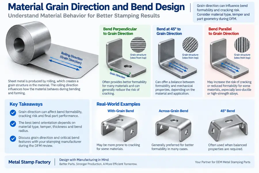
Sheet metal coils possess a directional grain structure created during the mill rolling process. Understanding how grain direction interacts with part geometry is vital for controlling formability and springback in metal stamping design guidelines.
Grain Direction
Metal grain runs parallel to the rolling direction of the coil stock. The orientation of bends relative to this grain direction can influence cracking risk depending on material alloy and temper:
- Bending Perpendicular to Grain (Across Grain): Bending across the grain places tensile stresses along the longitudinal direction of the metal fibers, which can generally reduce cracking risk during severe forming.
- Bending Parallel to Grain (With Grain): Bending along the grain separates adjacent metal fibers, increasing the risk of surface fracturing on less ductile or hard-temper materials.
- Diagonal Bending (45 Degrees): When a component features multiple bends orthogonal to each other, orienting the part layout at an angle relative to the coil progression helps balance forming severity across different bend lines.
While perpendicular bending is generally favorable for formability, component nesting efficiency in progressive dies often dictates layout orientation. DFM reviews help balance material utilization against formability constraints.
Springback Considerations
Springback occurs when stamped metal relaxes elastically after the press stroke releases forming pressure. The magnitude of springback depends on yield strength, elastic modulus, material thickness, and inside bend radius.
From a geometric DFM perspective, springback can be managed by:
- Specifying larger radii where acceptable to allow predictable compensation in tool design.
- Incorporating stiffening ribs or stiffening gussets across bend lines to mechanically reinforce the formed angle.
- Designing component geometry that minimizes unsupported flat spans in formed zones.
Burr Direction and Cut-Edge DFM Considerations
During metal punching and blanking, the cut edge develops a natural orientation relative to punch entry and breakout.
Burr direction plays a practical role in part assembly and functional performance. OEM engineers should consider cut-edge orientation during geometric design:
- Mating Surface Orientation: Design parts so that the cut-edge burr faces away from sliding contact surfaces, gaskets, or sensitive electrical wire routing.
- Forming Direction: Bending with the burr on the inside of the bend radius helps manage edge stress, as the burr edge is held under compression rather than extreme tension.
- Assembly Clearance: Account for cut-edge orientation when designing close-tolerance mechanical interlocks.
Detailed specifications regarding edge shear zones, burr height limits, and deburring methods should be addressed separately during quality planning.
Progressive-Die-Specific Geometry Considerations
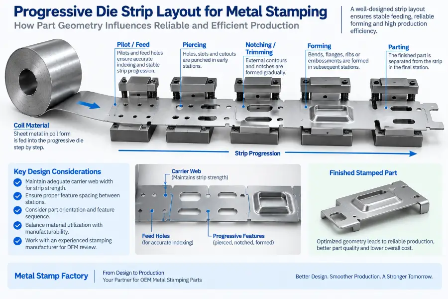
High-volume metal stamping predominantly utilizes progressive dies, where a continuous coil strip feeds through sequential operations at high speeds. Designing parts for progressive die production introduces specific geometric considerations related to strip handling.
Key progressive die DFM factors include:
- Carrier Web and Pitch: Parts remain connected to a continuous carrier strip as they move from station to station. Part geometry must provide reliable attachment points (tabs or webs) that stabilize the component during high-speed feeding.
- Pilot Hole Placement: Progressive dies rely on precision pilot pins entering pre-punched holes to position the strip accurately at each station. Incorporating dedicated pilot holes in off-part scrap or functional part geometry ensures precise station-to-station alignment.
- Feature Sequencing: Features located close to each other or near formed flanges may need to be produced in separate die stations. Designing balanced, symmetrical feature layouts simplifies die layout and lowers tooling costs.
- Strip Layout Efficiency: Minor adjustments to part geometry—such as changing an external radius or squaring an unused corner—can significantly improve material nesting, reducing coil scrap and unit cost.
Common Metal Stamping Design Mistakes
Avoiding frequent design errors speeds up tool development and eliminates avoidable manufacturing delays.
Common metal stamping DFM mistakes include:
- Applying Press-Brake Fabrication Rules to Stamping: Assuming that low-volume prototype press-brake capabilities transfer directly to high-speed progressive hard tooling.
- Undersized Pierced Features: Specifying hole diameters too small relative to sheet thickness and material strength, leading to frequent punch breakage.
- Placing Features in Forming Zones: Locating holes, slots, or cutouts too close to bend radii without providing bend relief, causing severe feature distortion.
- Ignoring Material Temper and Strength: Treating all sheet metals identically, leading to unexpected cracking on hard tempers or severe springback on high-strength alloys.
- Specifying Sharp Inside Corners: Omitting fillet radii on internal notch profiles, creating severe stress risers in both part and tool steel.
- Neglecting Grain Direction on Hard Materials: Specifying severe bends parallel to the coil rolling direction on low-ductility metals.
- Designing Overly Narrow Tabs or Webs: Creating delicate geometric projections that bend, twist, or jam during strip progression and part handling.
- Finalizing Geometry Without Supplier DFM Review: Releasing drawings for tooling production before confirming die access, clearance, and strip layout feasibility with the stamping manufacturer.
How OEM Engineers Should Prepare a Part for DFM Review
To streamline the transition from design to production, OEM engineers should prepare a comprehensive DFM package before freezing drawings or releasing tooling funds.
An effective DFM review package should include:
- Clean 3D CAD Models: Native or step files representing nominal geometry without embedded drafting artifacts.
- Fully Dimensioned 2D Drawings: Engineering drawings that clearly distinguish functional mating surfaces from non-critical profiles.
- Material Specifications: Complete material callouts specifying alloy grade, temper, thickness tolerance, and acceptable alternative materials.
- Production Volume Expectations: Annual volume forecasts and batch sizes, which dictate whether single-station, compound, or progressive tooling is most economical.
- Critical-to-Quality (CTQ) Identification: Clear markings on critical functional dimensions, allowing tool designers to prioritize station layout and die steel selection.
- Secondary Operation Requirements: Information regarding post-stamping requirements, such as heat treatment, plating, or automated assembly interface requirements.
| Review Item | OEM Requirement |
|---|---|
| CAD Model | Provide clean 3D geometry without unnecessary features |
| Drawing | Identify critical dimensions and functional surfaces |
| Material | Specify alloy, temper, thickness, and alternatives |
| Volume | Define annual demand and production expectations |
| CTQ Features | Identify critical-to-quality dimensions |
| Secondary Operations | Define plating, heat treatment, assembly requirements |
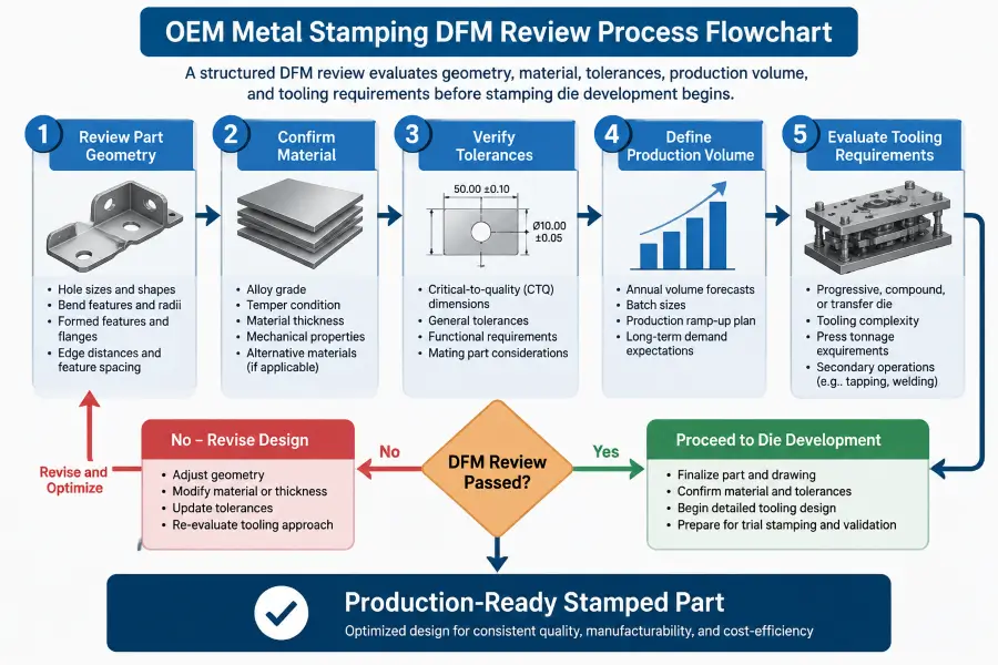
Collaborating early with an experienced metal stamping manufacturer ensures that geometry is optimized for high-speed press performance, long tool life, and consistent part quality.
Frequently Asked Questions
What are the most important metal stamping design guidelines?
The most important metal stamping design guidelines involve scaling part geometry to material thickness and material properties. Key considerations include evaluating hole-to-thickness ratios, placing holes outside of bend deformation zones, providing proper bend relief, using generous inside bend radii, avoiding sharp internal corners, and accounting for material grain orientation during forming.
What is the minimum hole size for metal stamping?
A hole diameter roughly equal to stock thickness is often referenced as a preliminary rule of thumb for ductile low-carbon steel. However, minimum hole size is not a universal constant or guaranteed tooling limit. It depends heavily on material tensile strength, punch strength, die clearance, and required tool life. Harder materials or high-strength alloys typically require larger ratios to maintain punch integrity.
How close can a hole be to a bend in a stamped part?
To prevent feature distortion, holes should be placed outside the active plastic deformation zone of the bend. Preliminary DFM guidelines recommend maintaining clearance between the hole edge and the bend radius based on material thickness and inside radius parameters. If features must be located closer, bend relief slots or post-bend punching operations should be evaluated during DFM.
Why should sharp internal corners be avoided in stamped parts?
Sharp internal 90-degree corners create extreme stress concentrations in both the stamped part and the stamping die punches. Sharp punch corners chip easily and wear rapidly under high-speed production. Adding generous radii to internal corners strengthens tool steel, lowers punching force, and extends die life.
How does material grain direction affect stamped bend design?
Coil-fed sheet metal has a longitudinal grain orientation from rolling. Bending perpendicular to (across) the grain can generally reduce cracking risk during severe forming operations. Bending parallel to (with) the grain increases the likelihood of surface fracturing, particularly in high-strength or hard-temper alloys.
What is the difference between sheet metal fabrication design guidelines and metal stamping DFM?
Sheet metal fabrication relies on flexible equipment like laser cutters and press brakes, which accommodate sharp corners and tight feature placement easily at lower volumes. Metal stamping uses custom hard tooling running at high speeds. Stamping DFM must account for punch structural integrity, die wall thickness, high-cycle tool fatigue, strip feeding stability, and material flow within enclosed die cavities.
Summary
Successful metal stamping design relies on balancing part functionality with the physical realities of sheet metal forming and die construction. Good DFM is not about adhering rigidly to a single universal table of minimum dimensions; it is about harmonizing part geometry, material thickness, temper, tooling architecture, and production volume requirements.
By applying robust design guidelines early in the CAD modeling stage, OEM engineers eliminate costly tool modifications, extend die life, and achieve reliable, repeatable high-volume manufacturing.
Before finalizing component designs or releasing drawings for hard tooling, submit your CAD models and drawing requirements to Metal Stamp Factory for a comprehensive engineering DFM review. Our technical team evaluates material selection, geometry ratios, strip progression, and tooling parameters to optimize your component for cost-effective, high-quality production.