Founder & International Sourcing Manager of Metal Stamp Factory, with more than 25 years of hands-on experience in tooling development, metal stamping, and OEM manufacturing.
Metal Stamp Factory / Xiamen Yichong Precision Hardware Manufacturing Co., Ltd. was established in Xiamen, China in 2014.
Quick Answer
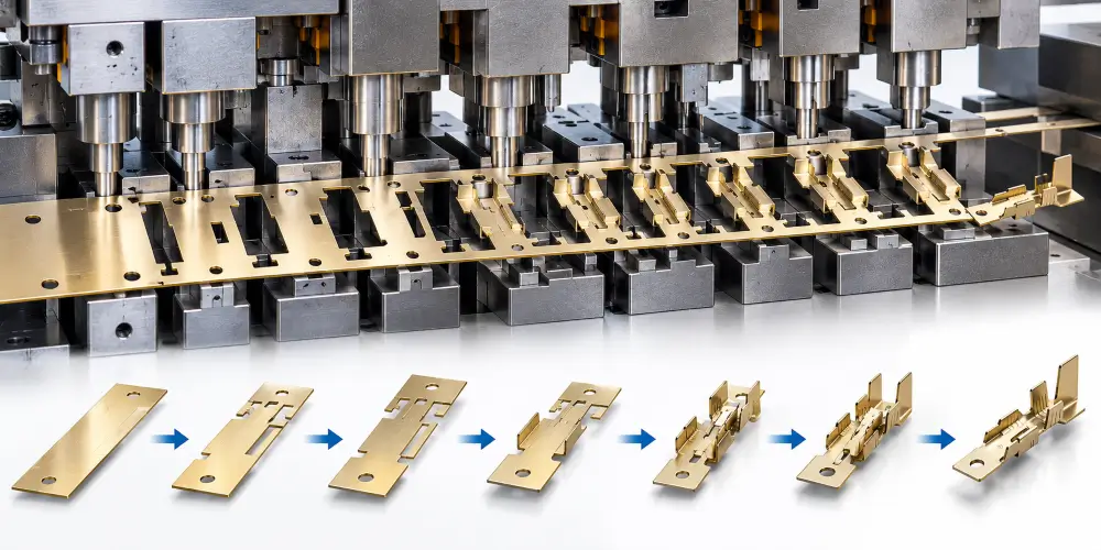
Progressive die stamping for electrical terminals is commonly used when a design combines thin strip, multiple formed features, and a need for consistent pitch and repeatability across larger production runs.
This article focuses on how electrical-terminal geometry changes progressive strip planning. It covers strip layout, carrier strategy, feed pitch, station sequencing, feature timing, burr-direction control, cut-off method, and the process risks that matter most when the part is a terminal rather than a generic stamped component.
When Progressive Die Stamping Fits Electrical Terminals
Suitable Production Conditions
Progressive die stamping is often a strong fit when an electrical terminal has repeatable features that can be produced in a controlled strip sequence. Typical conditions include:
- multiple piercing, forming, and cut-off operations that benefit from being integrated into one tool;
- the need for consistent pitch and feature-to-feature relationships across larger quantities;
- geometries that can be supported by a stable carrier strip during forming;
- a production plan that justifies dedicated progressive tooling;
- downstream needs such as reel delivery or controlled orientation for later processing.
In these cases, progressive die stamping allows the strip to advance through sequential stations so that each press stroke completes a defined set of operations on the advancing material.
When Another Process Route May Be Better
Progressive tooling is not the default answer for every terminal program. Another route may be more practical when:
- volume is low and dedicated progressive tooling is difficult to justify;
- the geometry is better suited to single-hit, compound, or secondary forming methods;
- the part requires process steps that do not integrate cleanly into a continuous strip;
- early development still needs frequent design changes before the geometry is stable.
Process selection should follow the actual drawing, expected production volume, and downstream plan rather than a general preference for progressive dies.
Why Terminal Geometry Changes Progressive Strip Planning
Feature Density and Local Forming Risk
Electrical terminals often pack several functional features into a small area: crimp barrels or wings, locking tabs or lances, mounting or locating holes, contact zones, and mating interfaces. That feature density changes strip planning.
Local forming risk rises when bends, lances, and pierced openings sit close to one another. Material movement in one station can disturb a nearby feature if the sequence is poorly ordered. Strip layout and station timing must therefore protect critical geometry while the part is still attached to the carrier.
Functional Surfaces That Drive Sequence Decisions
Not every surface on a terminal has the same functional importance. Contact zones, crimp interfaces, locking edges, and mating faces often matter more than non-functional edges. Sequence decisions should prioritize:
- access to features that must be pierced or formed cleanly;
- control of distortion around functional areas;
- preservation of datum relationships needed for pitch and assembly;
- protection of surfaces that will later be plated, inserted, or engaged in automated handling.
For electrical terminals, progressive planning is therefore driven by geometry and functional relationships rather than by a generic station checklist.
Strip Layout and Carrier Strategy
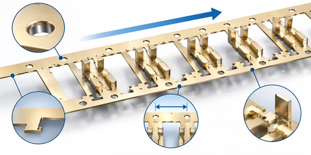
Carrier Design and Carrier Stability
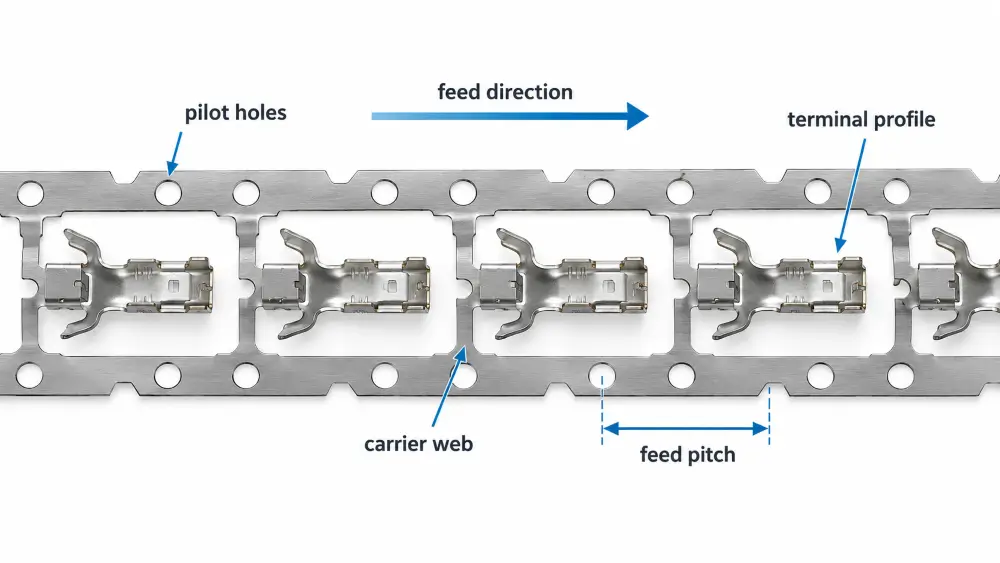
In progressive die stamping for electrical terminals, the carrier strip does more than transport the part between stations; it also contributes to process control.
A stable carrier helps maintain strip location as the material advances through piercing and forming stations. Poor carrier design can allow twist, lateral shift, or local deformation that later appears as pitch error, feature misalignment, or unstable cut-off conditions.
Carrier strategy must consider:
- how much material remains to support the terminal during forming;
- whether the carrier can resist distortion from nearby operations;
- how the part will eventually separate without damaging functional features;
- whether the strip must remain intact for reel delivery or downstream handling.
Carrier stability should be established as part of the strip-layout strategy rather than addressed later as a corrective measure.
Feed Pitch, Pilots, and Strip Location Control
Feed pitch defines the advance distance of the strip with each press stroke. For electrical terminals, pitch accuracy often affects both manufacturing consistency and downstream assembly fit.
Pilots and other strip-location features help register the material as it moves through the die. Their placement and timing should support the dimensional relationships that matter for the terminal, not merely serve as generic strip-guiding features.
Important planning questions include:
- Which features define the functional pitch or spacing requirement?
- Where can pilots be placed without interfering with critical forming?
- How will strip location be maintained after major piercing or forming stations?
- Which finished dimensions depend on strip pitch and registration?
Pitch control is especially important when terminals remain connected on a strip or reel for later processing.
Strip Progression and Material Utilization
Strip progression is the planned order in which the terminal develops as the strip advances. Efficient progression balances process stability with material utilization.
For terminals, material utilization matters, but it should not override carrier stability or feature integrity. Overly aggressive nesting can leave insufficient support around formed areas or force difficult cut-off conditions. A practical strip layout protects process control first and then improves utilization within that constraint.
Station Sequencing for Electrical Terminals
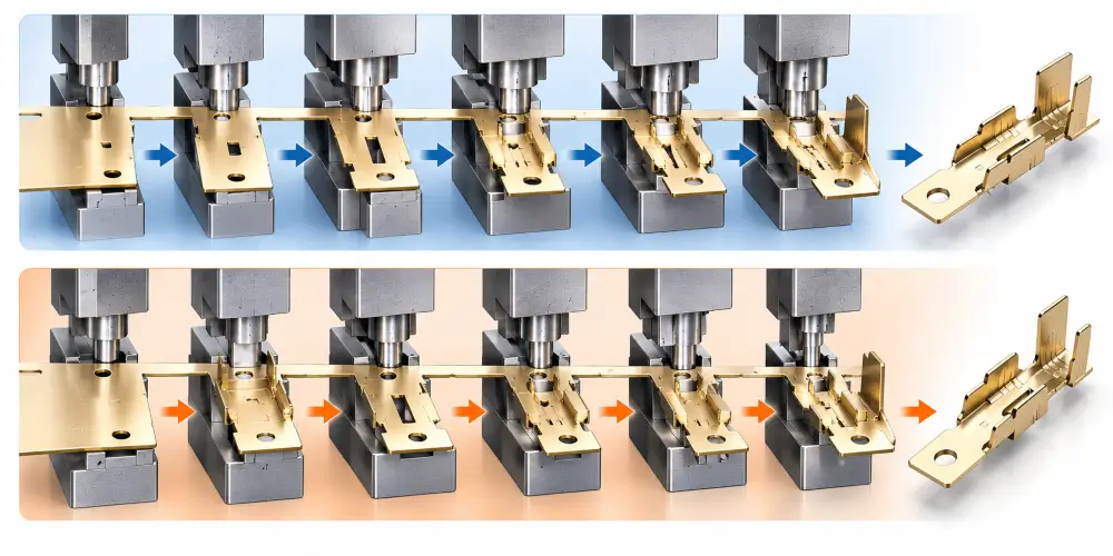
Piercing, Forming, and Feature-Timing Logic
Station sequencing determines when piercing, forming, coining, and separation operations occur. There is no universal rule that every opening must be pierced before every form. The correct order depends on:
- feature accessibility;
- risk of distorting an already formed area;
- datum strategy;
- tool construction constraints;
- the need to protect functional surfaces.
Some openings are best pierced early so later forms can be developed around a stable reference. Other features may need to be formed first, or staged across multiple stations, to reduce local strain or improve dimensional control. The sequence should be justified by the terminal geometry rather than by habit.
Crimp Wings, Locking Features, and Mating Areas
Crimp barrels or wings, locking tabs, locking lances, and mating surfaces are among the features that most strongly influence station timing.
Crimp-related forms often require controlled bending and consistent open geometry. Locking features may need precise lance or tab development without weakening adjacent areas. Mating or contact zones may require coining, controlled thickness, or protection from damage during later stations.
These features should be mapped early in strip planning so that:
- one forming stage does not disturb geometry established in an earlier station;
- critical edges are not disturbed after they are established;
- the cut-off method does not damage the functional geometry;
- the finished terminal remains compatible with downstream handling.
Cut-Off Strategy and Part Separation
Cut-off is the final separation of the terminal from the carrier strip. The method matters because it affects edge quality, orientation, and whether the part leaves the die as a loose component or remains attached to a carrier strip.
Planning questions include:
- Should the terminal be fully separated in the die?
- Should it remain attached for reel or carrier-strip delivery?
- Where is the safest separation location relative to functional features?
- How will separation affect burr location and edge condition?
Cut-off strategy should be planned in conjunction with the delivery format and downstream process requirements.
Burr Direction, Dimensional Relationships, and Process Risk
Burr Direction Relative to Functional Surfaces
Burr orientation is influenced by the cutting direction and the punch-entry side of the strip. On electrical terminals, burr orientation can matter when it interacts with:
- crimp interfaces;
- mating or contact surfaces;
- locking edges;
- assembly or insertion directions.
Burr direction should be evaluated relative to the functional surface and the assembly method. Burr orientation does not determine electrical performance on its own, but an uncontrolled burr on a functional edge can affect fit, insertion, crimping, handling, downstream finishing, or local stress during assembly.
Pitch Accuracy and Critical Dimensional Relationships
Electrical terminals often depend on relationships rather than isolated dimensions. Common examples include:
- spacing between repeated terminals on strip;
- location of a contact zone relative to a mounting or locking feature;
- consistency of crimp geometry relative to a datum;
- alignment needed for automated placement or insertion.
Progressive strip planning must protect these relationships through pilot strategy, station timing, and carrier control. Dimensional verification later in the process is important, but the relationships themselves should be designed into the strip progression.
Material Condition and Forming Margin
Thickness, Temper, and Geometry Interaction
Copper, brass, phosphor bronze, and in some cases stainless steel are all used for electrical terminals. Material family alone does not determine process margin. Thickness, temper or mechanical condition, and local geometry interact during piercing and forming.
A terminal that forms reliably in one condition may show greater springback, a higher risk of edge cracking, or more dimensional variation in another. Strip layout and station sequencing should be reviewed against the actual material condition specified on the drawing, not against a generic material label.
Springback and Forming Risk
Springback can affect flange angles, contact geometry, and overall dimensional stability. Its influence depends on material condition, thickness, bend severity, and forming sequence.
Some terminal features may need staged forming or compensation strategies. Others may be stable with simpler station plans. Springback should be treated as a geometry- and condition-dependent risk, not as a fixed property of a material family.
Tool wear and maintenance requirements also vary with the actual production conditions. Relevant factors include alloy, temper, thickness, lubrication, punch-to-die clearance, feature geometry, production volume, and overall tooling condition. These factors should be reviewed during process planning rather than reduced to a universal material ranking.
Downstream Constraints That Influence Strip Design
Reel and Carrier-Strip Delivery
Some electrical terminal programs keep parts on a carrier strip or reel for later processing or automated handling. That requirement changes cut-off strategy, carrier design, pitch control, and packaging logic.
If the terminal must arrive oriented and attached, the strip plan must preserve carrier integrity through the final stations. If the part is to be separated in the die, the cut-off method and part-handling plan change accordingly.
Plating, Insert Molding, and Automated Assembly
Downstream processes often impose constraints on the stamped terminal.
Selective plating may require specific surface conditions, orientation, or protection of functional zones. Insert molding may depend on consistent terminal geometry and stable strip presentation. Automated assembly typically needs predictable orientation, pitch, and feature integrity.
These requirements should be identified early because they influence whether the terminal is separated, left on strip, formed in a particular sequence, or protected at certain edges.
Dimensional Verification for Progressive-Stamped Terminals
Dimensional verification confirms that critical relationships remain under control after the process is established. For progressive-stamped terminals, verification often focuses on:
- pitch and spacing relationships;
- critical formed geometry;
- hole or slot locations relative to functional datums;
- features that affect crimp, lock, or mating function.
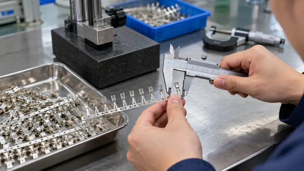
At Metal Stamp Factory, first-article inspection and periodic production sampling are performed using practical measuring tools such as vernier calipers, micrometers, and height gauges. The inspection plan follows the approved drawing’s critical dimensions, including pitch, formed geometry, hole or slot locations, and features affecting crimping, locking, or mating functions. Periodic sampling also helps identify dimensional changes associated with tooling wear.
What Should an OEM Specify on the Drawing and RFQ?
A progressive-die terminal program is easier to evaluate when the drawing and RFQ clearly identify the functional and manufacturing requirements. Useful information includes:
- Terminal geometry — complete 2D drawing and, where available, 3D data.
- Material designation and condition — alloy family, temper or mechanical condition, and any required standard.
- Material thickness and tolerance — especially where forming or contact geometry depends on it.
- Critical functional features — crimp barrels or wings, locking tabs or lances, contact zones, mating surfaces.
- Critical dimensional relationships — pitch, spacing, datums, and assembly-related positions.
- Burr or edge requirements — where functional surfaces are sensitive.
- Delivery format — loose part, carrier strip, or reel.
- Downstream requirements — plating, insert molding, automated assembly, or orientation needs.
- Inspection and documentation expectations — first-article needs and critical-to-quality dimensions.
- Expected production volume — to support tooling and process-route review.
Clear inputs allow the stamping supplier to evaluate strip layout, carrier strategy, station sequence, and process risk before tooling design is finalized.
Metal Stamp Factory Progressive Die Stamping Experience
Metal Stamp Factory is the export brand of Xiamen Yichong Precision Hardware Manufacturing Co., Ltd., based in Xiamen, China. Established in 2014, the business focuses on custom drawing-driven metal stamping and OEM production.
Our in-house tooling team handles custom die design and assembly after the customer confirms the part drawing and project requirements. Typical progressive die development takes 35–40 days, depending on part complexity and tooling scope.
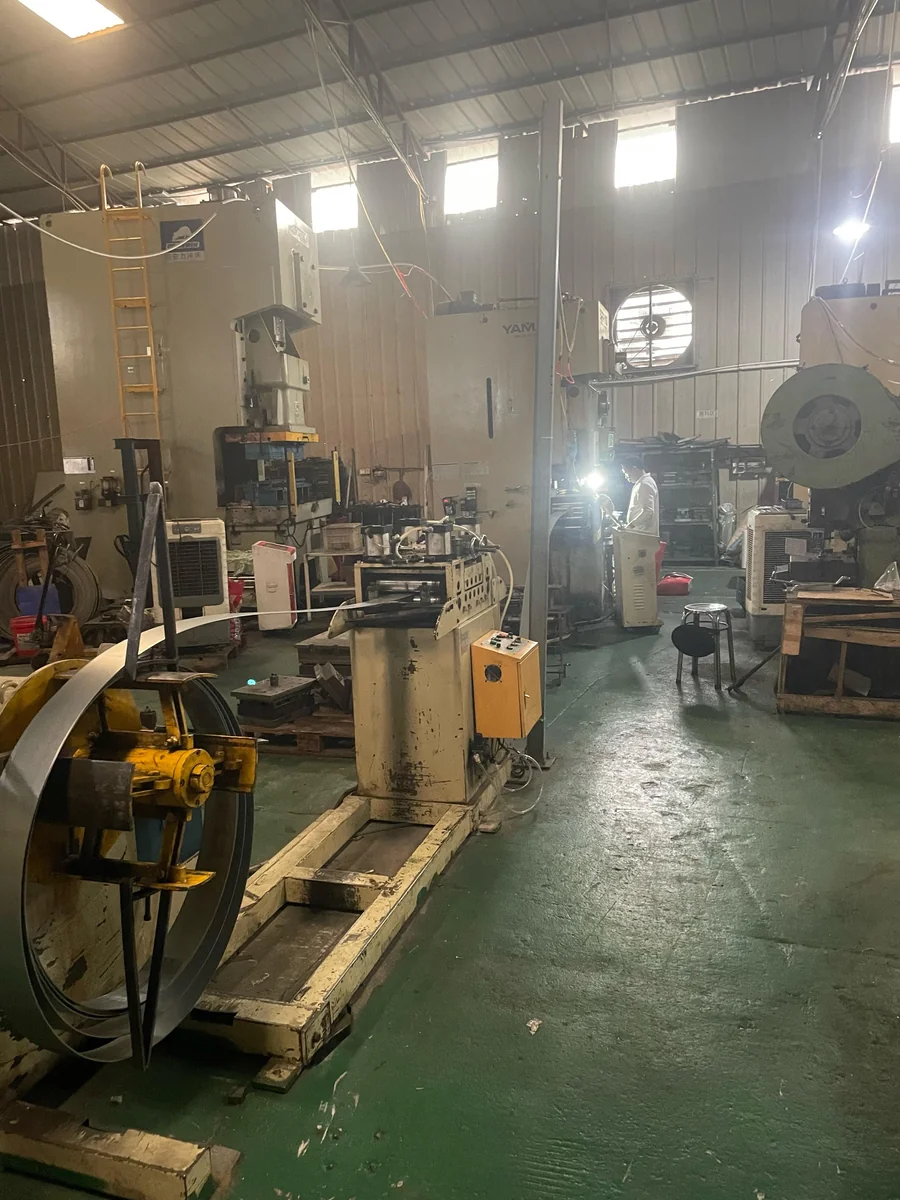
Progressive stamping, piercing, forming, and dimensional inspection are handled within our core manufacturing operations. Electroplating and other specialized secondary processes are coordinated through partner facilities where required.
Frequently Asked Questions
Is progressive die stamping suitable for every electrical terminal?
No. Progressive die stamping is often suitable for terminals that need integrated multi-step production, consistent pitch, and repeatable production at higher volumes. Low production volume, a design that is still changing, or geometry that does not suit continuous strip progression may favor another route.
Why are progressive dies commonly used for electrical terminals?
Because many terminals combine piercing, forming, and separation operations that can be organized into a controlled strip sequence. When geometry and volume support the approach, progressive tooling helps maintain feature relationships and production consistency.
How does carrier-strip stability affect electrical terminal quality?
A stable carrier helps maintain strip location during piercing and forming. If the carrier shifts, twists, or deforms, pitch accuracy and feature alignment can drift before the terminal is separated.
Should holes and slots always be pierced before forming?
No. Piercing and forming order should follow geometry, feature access, distortion risk, datum strategy, and tooling design. Some openings are best pierced early; others may need later timing or staged operations.
Why does burr direction matter on electrical terminals?
Burr orientation can affect functional edges, assembly fit, handling, or downstream plating if it sits on a critical surface. Its importance depends on the surface function and the assembly method.
Can stamped electrical terminals remain on a carrier strip or reel after stamping?
Yes. Some programs require carrier-strip or reel delivery for plating, insert molding, or automated assembly. That requirement must be built into cut-off strategy and carrier design.
What information should an OEM include in a progressive-die terminal RFQ?
Provide the drawing, material and thickness, critical terminal features, dimensional relationships, delivery format, downstream process needs, expected production volume, and inspection requirements. These inputs directly affect strip planning and tooling review.
Send Your Electrical Terminal Drawing for Process Review
If you are evaluating progressive die stamping for an electrical terminal, provide the current drawing, material and thickness, critical crimp or locking features, contact or mating areas, plating requirements where applicable, carrier or reel needs, downstream insert-molding or automated-assembly constraints, expected production volume, and inspection or documentation requirements.
Metal Stamp Factory can review the terminal geometry against strip layout, carrier strategy, station sequencing, and process feasibility before quotation and tooling planning.