Founder & International Sourcing Manager of Metal Stamp Factory, with more than 25 years of hands-on experience in tooling development, metal stamping, and OEM manufacturing.
Metal Stamp Factory / Xiamen Yichong Precision Hardware Manufacturing Co., Ltd. was established in Xiamen, China in 2014.
Stamped mounting brackets are drawing-defined sheet-metal components used to locate, support, fasten, or position other parts in an assembly. The main manufacturing challenge is usually the relationship between holes, bends, flanges, offsets, and mounting faces rather than any one dimension by itself.
For OEM engineers and buyers, the real question is not simply whether a bracket can be stamped. The part also has to hold the intended geometry from production through inspection and then fit the mating assembly without forcing, shimming, or avoidable rework.
What Are Stamped Mounting Brackets?
Stamped mounting brackets are made from sheet metal through operations such as blanking, piercing, bending, and forming. Depending on part geometry and production requirements, these operations may be completed in separate tools or combined into progressive tooling.
Unlike standard catalog hardware, custom stamped mounting brackets are defined by the customer drawing. Material, thickness, hole pattern, formed height, flange angle, functional surfaces, finish, and other requirements are selected around the mating assembly.
Two brackets can look similar and still require very different tooling and inspection plans. A small change in hole position, offset, flange length, or material condition can change the forming sequence and the way final geometry is checked.
Common Mounting Bracket Geometries and Features
Mounting brackets often begin with familiar L-, U-, Z-, or offset forms, but the geometry that matters in production is usually more detailed than the overall profile.
| Geometry or feature | Typical function | Manufacturing point to review |
|---|---|---|
| L-shaped bracket | Creates two mounting planes at an angle | Bend angle, flange length, hole position relative to the bend |
| U-shaped or channel bracket | Locates or supports a component between two flanges | Parallelism or relative flange position, formed width, springback |
| Z-shaped / offset bracket | Connects mounting planes at different heights | Offset height, cumulative bend variation, mounting-face relationship |
| Holes and slots | Fastening, adjustment, locating | Position relative to bends, distortion during forming, burr direction |
| Tabs / formed ears | Locating or secondary attachment | Forming sequence, local distortion, access for tooling |
| Ribs / beads / embosses | Increase local stiffness or create functional features | Material flow, proximity to holes/bends, available forming space |
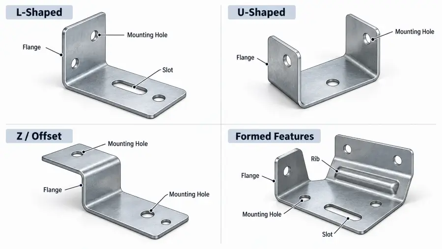
These features should be reviewed as a system. A hole may be correct in diameter but still create an assembly problem if its final position changes after a nearby bend. Likewise, a flange may meet its nominal angle while the finished mounting surface sits too high, too low, or twisted relative to another face.
What Makes a Mounting Bracket Difficult to Stamp Accurately?
Many stamped metal brackets look simple when viewed as flat blanks. The difficulty appears after several features begin to interact.
A bend changes material flow near holes and slots. Springback changes the final position of a flange after the die opens. Multiple bends can accumulate variation in formed height or offset. Residual stress can leave a mounting face bowed or twisted even when several individual dimensions remain acceptable.
Bracket drawings are easier to manufacture when they distinguish between general dimensions and the features that actually control assembly. For one part, a hole pattern may be the main functional requirement. For another, the relationship between two mounting faces may matter more than the overall outside size.
From a tooling standpoint, the goal is not to make every dimension equally difficult to control. It is to understand which features determine fit and then plan the process around those relationships.
Hole and Slot Position Relative to Bends
Holes and slots close to a bend can distort as the material is formed. Depending on the geometry, the opening may elongate, shift, or lose its intended relationship to the bend line.
The risk is influenced by several factors, including material thickness, material condition, bend radius, hole or slot geometry, remaining web, and forming sequence. For that reason, a single universal hole-to-bend rule is not appropriate for every stamped mounting bracket.
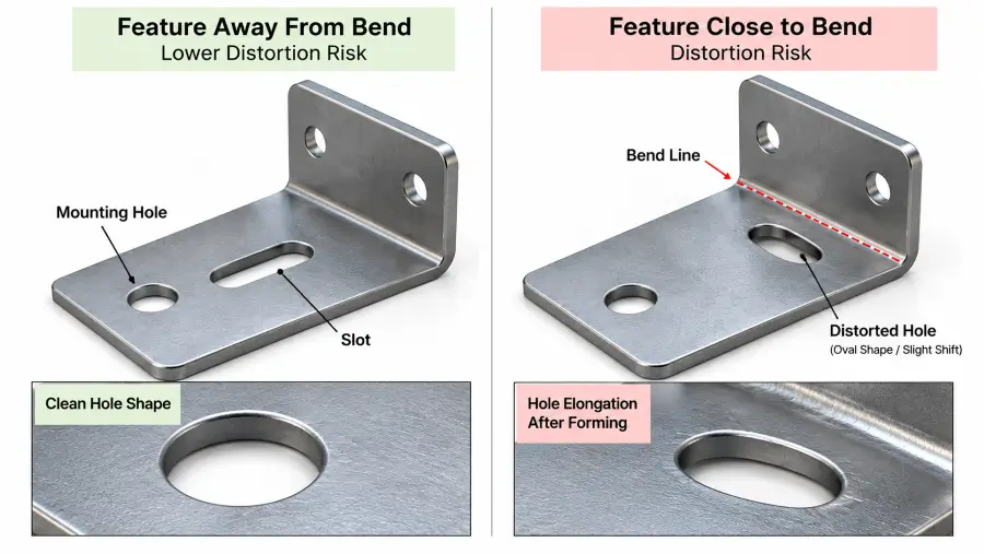
What matters is whether the hole is merely a clearance feature or whether it locates a fastener, pin, or mating component. If its position is functionally important, that relationship needs to be reviewed during DFM and tooling development. The same feature-spacing logic is covered in our metal stamping design guidelines.
Slots deserve the same attention. They can provide assembly adjustment, but a slot placed in a heavily formed area may also distort. When the slot itself is intended to absorb assembly variation, its purpose should be clear from the drawing rather than inferred after tooling starts.
Bend Radius, Flange Geometry and Formed Height
Bend radius, flange length, material thickness, and material condition all influence formability. Tight bends can increase cracking risk in some materials, while very short flanges may be difficult to support and form consistently.
For mounting brackets, formed height is often more important than the appearance of an individual bend. A bracket may use two or more bends to establish the final position of a mounting plane. Variation at each bend can accumulate and shift that plane relative to the rest of the part.
Offset brackets have the same problem. The finished offset comes from several formed features working together, so it is better treated as one functional geometry than as a set of unrelated bend angles.
When a dimension controls assembly, the drawing should identify it directly where practical. That gives the tooling and inspection plan a clear target.
Ribs, Beads and Embossed Features for Bracket Stiffness
Ribs, beads, and embosses can increase local stiffness by changing the section geometry of the sheet. They are often useful where a long flange, broad flat area, or local mounting region needs additional rigidity.
These features do not automatically mean a thinner material can be used. Whether a formed stiffening feature is appropriate depends on load, material, thickness, available space, surrounding bends, and the way the bracket is supported in the final assembly.
They also affect manufacturability. A bead running into a bend, a rib too close to a pierced feature, or an emboss added late in the design can complicate material flow and station planning. It is better to review these features as part of the bracket geometry than to treat them as decoration added after the main tooling concept is fixed.
Springback and Final Mounting Geometry
After a bend or form is released from the tool, elastic recovery can change the final angle or position. On stamped mounting brackets, springback may show up as a flange angle change, a different formed height, a shifted offset, or a mounting face that no longer sits where the drawing intends.
The effect becomes more important when several bends contribute to one functional relationship. Small changes at individual bends can accumulate in the final geometry even when no single bend appears dramatically wrong.
Tooling development may use staged forming, controlled over-forming, restrike operations, or other compensation methods where appropriate. The actual approach depends on the specified material, thickness, geometry, and production process; it should not be treated as a fixed correction value that applies to every bracket. Our springback in metal stamping guide explains the underlying forming behavior in more detail.
Flatness, Twist and Mounting-Surface Distortion
A bracket can pass checks for overall length, hole diameter, and several local dimensions yet still fail during assembly if a functional mounting face is bowed or twisted.
The problem becomes more visible when two surfaces need to contact a mating structure at the same time. If one face lifts or rotates relative to the other, tightening a fastener may pull the bracket into position rather than simply clamp it. That can create assembly stress, gaps, or inconsistent fit.
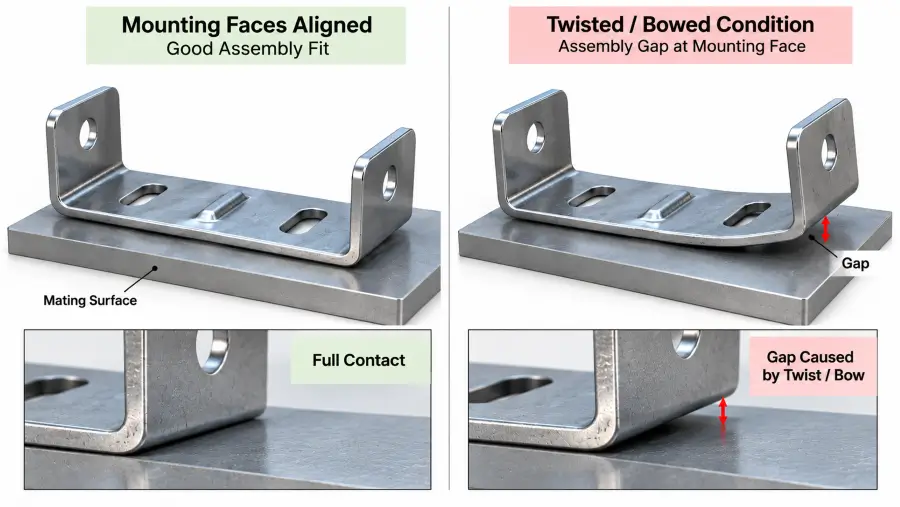
Inspection needs to follow the function of the part. If a particular face controls seating, or if two faces must maintain a specified relationship, the drawing should make that requirement clear. The measurement method can then be chosen around the actual acceptance condition instead of relying only on general outside dimensions.
Burr Direction and Functional Edges
Blanking and piercing produce a cut edge with different characteristics on the punch-entry and exit sides. The burr side can matter when a bracket must sit against another surface, slide into an assembly, contact insulation, or present an edge to an operator.
A burr on a functional seating face can prevent full contact or create a local high point. Beside a cable or insulating component, the same burr may create a different assembly risk.
When burr direction is functionally important, it should be identified on the drawing. The die layout and punch direction can then be planned with that requirement in mind rather than corrected later through unnecessary secondary work. More detailed edge-condition guidance is available in our metal stamping burr tolerance article.
Material Selection for Stamped Mounting Brackets
Material selection affects strength, corrosion behavior, formability, springback, finishing route, and cost. Common choices include low-carbon steel, stainless steel, aluminum, and coated steels. For the wider selection logic across stamped parts, see our metal stamping material selection guide.
- Low-carbon steel is widely used where general structural performance, formability, and cost need to be balanced. When a project specifies ASTM cold-rolled sheet, ASTM A1008/A1008M-26 is one relevant material specification.
- Stainless steel may be selected where corrosion resistance or material-specific service requirements matter. ASTM A240/A240M-26 covers stainless steel plate, sheet, and strip for general applications among other uses.
- Aluminum can reduce part weight, but its forming behavior and stiffness differ from steel and need to be considered in the design.
- Coated steel can provide corrosion protection while allowing the bracket to be formed from pre-coated sheet when the project permits it.
The drawing should specify material grade and thickness. Where temper, hardness, or material condition affects forming, that information also needs to be controlled.
For bracket design, material cannot be separated from geometry. Strength, corrosion exposure, forming demand, thickness, and finishing requirements all need to be considered together before tooling is finalized.
Choosing the Right Tooling Route for a Mounting Bracket
The tooling route depends on the bracket geometry, expected production quantity, number of pierced and formed features, repeatability requirements, and the economics of the project.
| Factor | Single-operation / stage tooling | Progressive die stamping |
|---|---|---|
| Typical use | Simpler parts, lower production demand, or projects where separate operations are acceptable | Repeating production with multiple pierced and formed features |
| Part handling | More handling between operations | Strip advances through sequential stations |
| Tooling investment | Generally lower than a more complex progressive tool | Generally higher because multiple operations are integrated |
| Feature relationship | Depends on control between separate operations | Can maintain feature relationships consistently once the die is developed and stable |
| Production planning | Flexible for simpler or changing requirements | Best suited when geometry and production demand justify dedicated tooling |
Single-Operation or Stage Tooling
A simple bracket may be blanked, pierced, and formed through separate operations. This can reduce initial tooling complexity, especially when production demand does not justify a dedicated progressive die.
The tradeoff is additional handling and the need to control part location from one operation to the next. Whether that matters depends on which dimensions are functional and how much variation the assembly can accept.
Progressive Die Stamping
Progressive die stamping combines a sequence of operations in one strip layout. Piercing, blanking, forming, local features, and final cut-off can be distributed across stations so the geometry develops in a controlled sequence.
For suitable custom stamped mounting brackets, this can reduce separate handling and improve repeatability of relationships between features. Progressive tooling is not automatically the best choice simply because a part will be produced repeatedly; the bracket geometry, quantity, material, tool complexity, and required secondary operations still need to justify the investment.
When Secondary Forming May Still Be Required
Some bracket features are more practical to complete after the main stamping operation. Deep offsets, difficult access conditions, local forms, or geometry that interferes with strip progression may require a secondary forming or restrike step.
The route is decided during tooling review. The priority is to produce the required geometry reliably, even when that means keeping one or more forming steps outside the main die.
From Our Production: A Progressive-Die Stamped Mounting Bracket
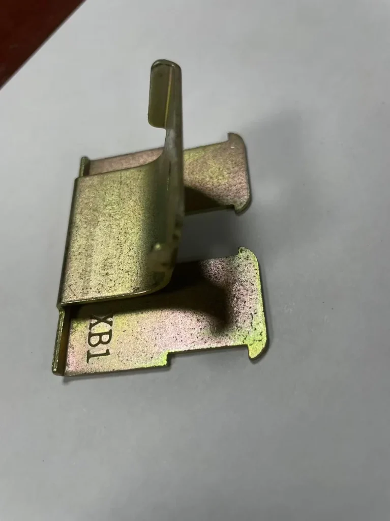
One real production example at Metal Stamp Factory is a motorcycle mounting bracket made with progressive-die tooling. The manufacturing sequence includes blanking, piercing, and bending/forming before the part receives a color zinc-plated finish.
For this part, we have real finished-part photographs, tooling and production imagery, dimensional inspection evidence, and production video. The useful point is the manufacturing sequence: a real mounting component moves through strip-based tooling, piercing and forming, dimensional verification, and finishing.
Real production footage showing progressive-die tooling used for the XB1 stamped mounting bracket.
The part also shows why bracket inspection cannot stop at individual dimensions. Several pierced and formed features have to remain in the correct relationship for the bracket to assemble as intended.
Surface Finish and Corrosion Protection
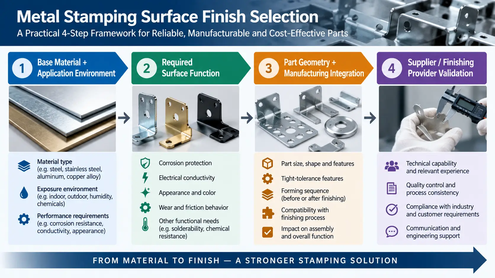
Surface finish is selected around the service environment, appearance, material, and drawing requirements. Common routes for stamped brackets can include zinc plating, other electroplated finishes, powder coating, or painted systems.
At Metal Stamp Factory, metal stamping, custom die design, and die assembly are handled in-house. Tooling development begins after the customer confirms the part drawing and project requirements. Typical progressive die development takes 35–40 days, depending on part complexity and tooling scope. Electroplating, powder coating, painting, heat treatment, and similar specialized secondary operations are coordinated through partner facilities where required.
The stamping process still affects finish quality. Sharp edge conditions, local deformation, trapped geometry, and the way a part contacts racks or other parts during finishing can influence the final result. Finish requirements therefore need to be known before the manufacturing route is finalized.
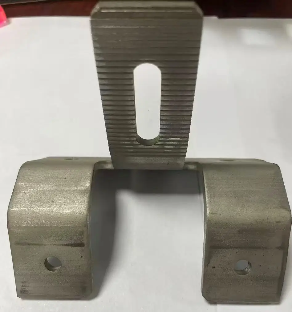
Another real production example is a W-type roofing mounting bracket made from DX51D+ZM275 coated steel. We have production imagery and video for this part as well. Here it is useful as a practical example of forming a bracket from pre-coated material.
Dimensional Inspection for Mounting Brackets
Inspection starts with the approved drawing and the features that control function. Metal Stamp Factory uses vernier calipers, micrometers, and height gauges for dimensional checks. First-piece dimensional inspection is performed before mass production, followed by periodic sampling during production to monitor dimensional consistency and identify potential changes associated with tooling wear. Our metal stamping quality inspection guide covers the broader inspection framework for stamped parts.
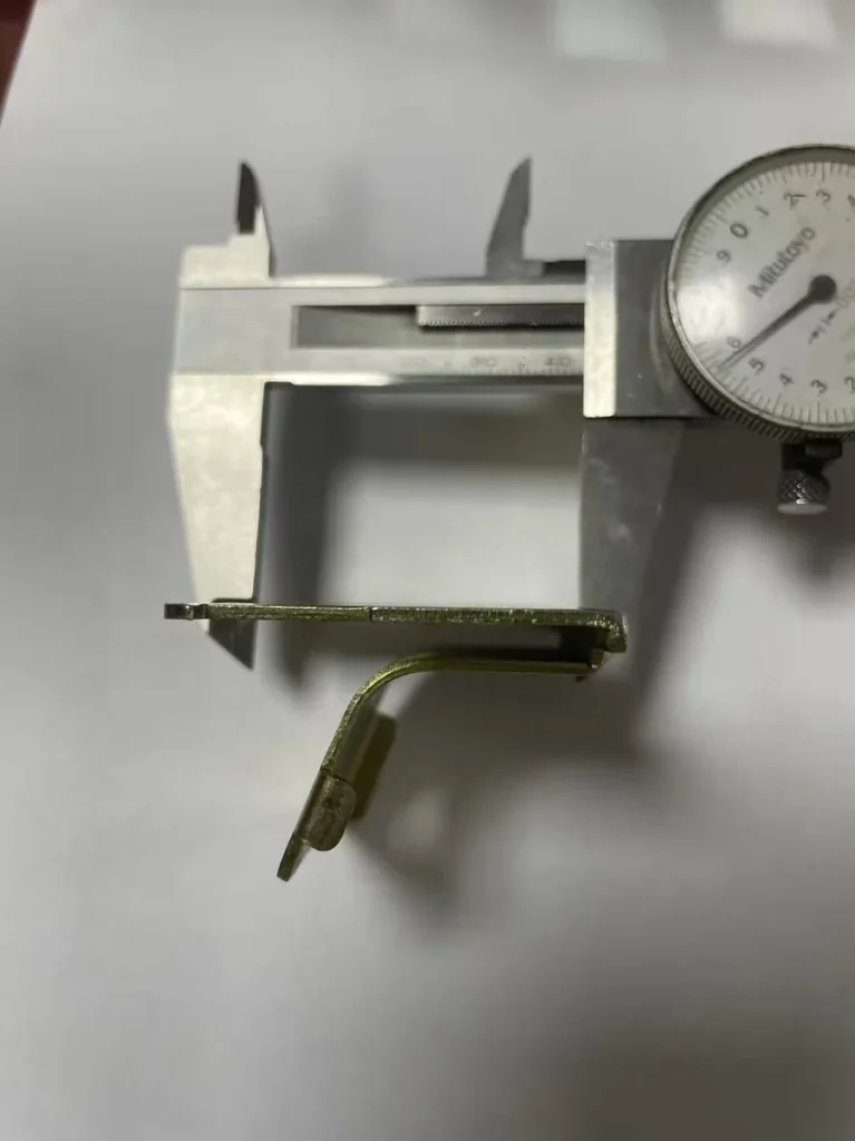
Not every bracket requires the same inspection priorities. Depending on the drawing, the important features may include hole spacing, hole position, formed height, flange location, overall width, or the relationship between functional mounting surfaces.
The inspection method also needs to match the feature being evaluated. A simple accessible dimension may be checked directly with a caliper, while a formed height may be better suited to a height gauge. Where a customer specifies requirements beyond available in-house inspection resources, independent inspection or testing can be coordinated externally when required.
What Should Be Defined on a Mounting Bracket Drawing?
A clear drawing reduces tooling assumptions and helps both sides focus on the dimensions that actually determine assembly.
| Drawing requirement | Why it matters for a stamped mounting bracket |
|---|---|
| Material grade and thickness | Affects forming behavior, springback, tooling, strength, and finish planning |
| Critical dimensions and tolerances | Identifies the features that require tighter process and inspection control |
| Datum / reference surfaces where relevant | Defines positional relationships between holes, flanges, and mounting faces |
| Hole and slot sizes / locations | Controls fastener fit, adjustment, and mating-part alignment |
| Formed height / flange geometry | Determines final mounting position and assembly relationship |
| Functional mounting surfaces | Helps define flatness, seating, and inspection priorities |
| Burr direction where relevant | Allows punch direction and die layout to reflect assembly needs |
| Finish requirements | Affects secondary-process planning and quotation |
| Inspection / documentation requirements | Clarifies what needs to be verified or supplied with the order |
The drawing does not need unnecessarily tight controls on every feature. It does need to make the functional requirements clear enough for tooling, production, and inspection to work toward the same result.
What OEM Buyers Should Include in a Mounting Bracket RFQ
For a useful manufacturing review and quotation, the RFQ should include the current 2D drawing, material and thickness, expected quantity or annual demand, finish requirements, and any dimensions or surfaces that are critical to assembly.
3D CAD data is helpful when available, especially for multi-bend or offset geometry. Notes about mating parts or the purpose of adjustment slots can also prevent incorrect assumptions during DFM review.
Sample expectations should be stated as well. If the project requires prototype parts before formal production tooling, the manufacturing route may differ from parts made after a production die is completed. If formal tooling is required, tooling and sample arrangements should be confirmed as part of the quotation rather than assumed from a prototype process.
Frequently Asked Questions
What materials are commonly used for stamped mounting brackets?
Low-carbon steel, stainless steel, aluminum, and coated steels are common choices. The correct material depends on strength, corrosion environment, weight, forming requirements, finish, and cost. Material grade and thickness should be defined on the drawing.
Can mounting brackets be produced with progressive dies?
Yes, many mounting brackets can be produced with progressive tooling when geometry and production demand justify it. Piercing, forming, local features, and cut-off can be distributed across multiple stations. Some designs still require secondary operations.
Why do holes near bends distort during bracket forming?
Material near a bend is stretched and compressed during forming. If a hole or slot is too close to that deformation zone for the selected material and geometry, its shape or final position can change. The risk needs to be reviewed using the actual thickness, bend radius, feature geometry, and forming sequence.
How does springback affect a stamped mounting bracket?
Elastic recovery after forming can change flange angle, formed height, offset, or the position of a mounting face. On multi-bend brackets, small changes at several bends can accumulate in the final assembly geometry.
Why does flatness matter on mounting surfaces?
A bowed or twisted functional face may prevent the bracket from seating correctly even if several individual dimensions are within tolerance. The drawing should identify mounting surfaces whose relationship is important to assembly.
When do ribs or embosses help stiffen a stamped bracket?
Ribs, beads, and embosses can increase local stiffness by changing the section geometry. Whether they are useful depends on load, material, thickness, surrounding features, available forming space, and the final assembly.
What information is needed to quote a custom stamped mounting bracket?
Provide the current 2D drawing, CAD data if available, material grade, thickness, quantity or annual demand, finish requirements, critical dimensions or functional surfaces, and any sample or documentation requirements.
Send Your Mounting Bracket Drawing for Review
If you are developing a custom stamped mounting bracket, send your 2D drawing, CAD data if available, material requirements, thickness, quantity, finish, and project specifications for manufacturing review and quotation. You can also review our custom metal stamping capabilities before submitting the project.
Metal Stamp Factory can review the bracket geometry, proposed stamping route, tooling requirements, and drawing information before quotation. Include any assembly or inspection requirements that are important to your application.