Founder of Metal Stamp Factory with more than 25 years of hands-on experience in tooling development, metal stamping, and OEM production.
Introduction
In sheet metal piercing operations, the material cut from the sheet—commonly referred to as a slug or scrap—is intended to break away cleanly and fall through the die opening. When process or tooling conditions disrupt this path, the slug can return upward with the punch or move unexpectedly into the strip area. This behavior is known as slug pulling, one of the common metal stamping defects that can appear during piercing operations.
A pulled slug introduces operational risks to a stamping die. If a loose piece of scrap settles between the strip and the die face, subsequent press strokes can press the scrap directly into the part surface or tooling components. Depending on the material, press force, and slug size, this can result in surface indentation, dimensional variation, or potential tooling wear.
Resolving slug pulling effectively requires a structured approach. Because different mechanical, surface, and operational factors can cause scrap to lift, modifying tools without a clear diagnosis can lead to unresolved issues or new tooling problems. A key guiding principle during troubleshooting is that where the slug is found is a diagnostic clue, not proof of a single root cause.
What Is Slug Pulling in Metal Stamping?
What Normally Happens to a Pierced Slug
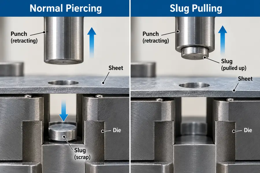
During a normal piercing operation, the punch enters the material, creating local deformation, shear, and fracture. As the punch completes its entry into the die opening, the separated scrap slug enters the die land or matrix.
As the punch retracts, the separated slug should remain below the strip and move through the die opening or designated scrap path. Its movement depends on the material, slug geometry, punch-to-die clearance, and any retention or evacuation features incorporated into the die. The punch then withdraws cleanly, leaving the scrap behind in the scrap chute or die matrix to be evacuated downward away from the strip.
What Happens During Slug Pulling
During slug pulling, the scrap fails to remain securely inside the die opening during the upward stroke of the punch. Instead, force mechanisms between the punch face and the slug can pull the scrap back toward the strip level.
Once the slug clears the top of the die matrix, it may remain attached to the punch face, adhere under the stripper plate, or move along the strip surface. In some instances, press motion, air currents, or strip movement can cause the slug to drop, leaving it resting loosely in the path of subsequent strokes.
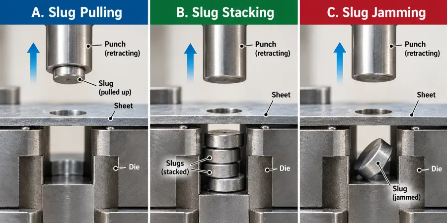
Slug Pulling vs. Slug Stacking vs. Slug Jamming
Distinguishing between different scrap movement problems helps focus troubleshooting efforts on the correct area of the die:
| Failure Mode | Main Behavior | Typical Concern |
|---|---|---|
| Slug Pulling | Slug returns upward with the punch or reaches the strip/tooling area. | Loose scrap may interfere with the part, strip, or tooling. |
| Slug Stacking | Multiple slugs accumulate in the die or scrap path instead of evacuating. | Accumulated scrap can interfere with normal scrap removal and tooling operation. |
| Slug Jamming | A slug becomes tilted or wedged in the die opening or scrap path. | Scrap blockage can interfere with tooling movement or evacuation. |
Why Does Slug Pulling Happen?
Slug pulling can occur when the forces acting to pull the slug upward exceed the forces keeping the slug downward inside the die opening.
Slug Adhesion to the Punch Face
The physical contact between a flat punch face and a freshly cut scrap slug can create surface adhesion. Stamping lubricants present on the material surface can form a thin fluid layer between the two surfaces. Under certain press and tooling conditions, this liquid film can create surface-tension adhesion, contributing to the slug lifting with the punch tip during withdrawal.
Punch-Face Suction or Air Entrapment
Air entrapment or pressure differences at the punch face can contribute under some conditions. Industry guidance on common causes of slug pulling discusses punch-face suction and related contributors in piercing dies. As the punch cuts through the sheet metal, air between the punch face and the material is displaced. Upon withdrawal, the interface between the punch tip and the slightly deformed slug can form a partial seal. The resulting pressure differential can contribute to suction that draws the scrap upward out of the die matrix.
Residual Magnetism
Under some tooling conditions, residual magnetism remaining in punches or die components after surface grinding or maintenance may contribute to slug attraction. Magnetic pull can act on ferrous scrap, overcoming light friction inside the die opening during punch retraction.
Punch-to-Die Clearance and Slug Retention
Punch-to-die clearance can influence how the slug deforms and interacts with the die opening. Wilson Tool provides additional industry background on die clearance and slug retention. Depending on the material, thickness, and tooling geometry, clearance may affect slug retention behavior. When clearance alters the lateral fit or compression of the scrap within the die opening, it can influence how easily upward forces might lift the slug.
Die-Side Retention Failure
If the die button or matrix land provides insufficient resistance to hold the slug, retention failure may occur. Changes in die-land surface condition or geometry can influence friction and the way the slug is retained. When die-side retention is reduced, punch-side adhesion or attraction may be more likely to carry the slug upward.
Punch or Die Condition
The physical state of the cutting edges can also influence slug behavior. The broader cutting-edge mechanics behind stamping burrs are covered separately. Punch corner rounding or edge condition can alter how material fractures and changes contact behavior. Similarly, the condition of the die entry edge can affect how securely the slug engages the die land, altering retention characteristics.
Punch-Side Causes vs. Die-Side Causes
To organize an investigation, potential causes can be evaluated based on where the primary contributor originates:
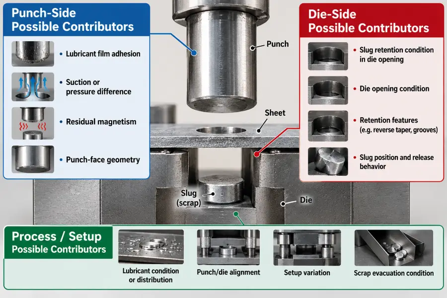
Punch-Side Contributors
- Surface Adhesion: Fluid film tension from stamping lubricants on the punch face.
- Punch-Face Suction: Pressure differentials created at the flat punch-and-slug contact area.
- Residual Magnetism: Magnetic forces retained in punch components post-grinding.
- Punch-Face Geometry: Flat punch contact profiles that can increase contact area against the scrap.
Die-Side Contributors
- Insufficient Retention: Die land conditions that fail to provide adequate frictional resistance.
- Die Opening Condition: Polished, worn, or altered die matrix entry lands.
- Retention Feature Condition: Where retention features are used, their condition, damage, or wear may affect slug retention.
- Slug Wedging or Release: Incomplete or uneven release of the slug within the upper die land.
Process / Setup Contributors
- Lubricant Condition: Quantity, distribution, or type of lubricant applied to the strip.
- Setup Variation: Inconsistencies during press setup or tool installation.
- Punch/Die Alignment: Alignment variations affecting edge contact or material clearance.
- Scrap Evacuation Condition: Conditions in the scrap path or existing evacuation path that may interfere with scrap exit.
Where the Slug Is Found Can Help Narrow the Cause
While the location of a loose slug helps guide the investigation, it serves as a diagnostic clue rather than proof of a single root cause.
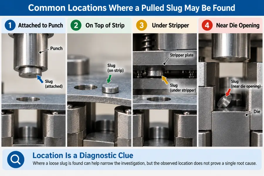
Slug Stuck to the Punch
If a slug remains attached directly to the face of the punch, the investigation should evaluate punch-side contributors. Lubricant film adhesion, punch-face suction, flat contact geometry, or residual magnetism are common factors to review in this scenario.
Slug Dropped Onto the Strip
A slug found on top of the strip may be consistent with a slug that was carried upward and released later in the stroke or feed cycle. Punch-side adhesion and die-side retention should both be reviewed before assigning a root cause.
Slug Found Under the Stripper or Tooling Surface
Scrap found under the stripper or near tooling surfaces may suggest that punch-side interaction contributed to upward movement, but the exact mechanism should be confirmed through inspection of the punch, die opening, lubricant condition, and scrap path.
Slug Wedged in the Die Opening
A slug tilted or partially lifted near the die opening may be associated with incomplete or uneven retention, slug orientation, or scrap-path interference.
Loose Slug Causing Part or Strip Damage
When a loose slug causes marks or indentations on stamped parts or the strip, the scrap has re-entered the active tooling space. While the surface impact occurs in the part area, the investigation must trace back to the source piercing station where the scrap was generated.
Intermittent vs. Repeatable Slug Pulling
Evaluating the frequency of slug pulling can help categorize potential contributors during troubleshooting:
Intermittent Slug Pulling
Intermittent slug pulling may point the investigation toward variable process or setup conditions, but frequency alone does not identify a single root cause.
Possible contributors may include:
- Lubricant variation across the material coil or run.
- Temporary adhesion caused by transient fluid buildup.
- Setup variation during production or material changes.
- Scrap-path disturbance or temporary blockage.
Repeatable Slug Pulling
Repeatable slug pulling may direct attention toward recurring punch–slug interaction, die-side retention, or consistent setup conditions, but it does not by itself prove a permanent tooling defect.
Possible contributors may include:
- Recurring punch-face interaction (such as flat surface adhesion or residual magnetism).
- Recurring die-retention behavior associated with die land condition or geometry.
- Repeatable setup condition affecting alignment or clearance.
- Recurring tooling condition following sharpening or maintenance.
How to Troubleshoot Slug Pulling
When investigating a slug pulling issue, systematic review of observed patterns can help focus corrective actions:
| Observed Pattern | Possible Contributors | What to Review |
|---|---|---|
| Slug sticks to punch | Adhesion, suction, residual magnetism, punch-face condition | Punch face, lubricant condition, tooling condition |
| Slug drops onto strip | Upward carry followed by release; insufficient retention | Punch–slug contact, die retention, setup consistency |
| Slug remains near die opening | Uneven or incomplete retention; scrap-path restriction | Die opening, slug position, scrap evacuation |
| Intermittent pulling | Lubricant variation, temporary adhesion, setup variation | Run-to-run consistency, lubrication, scrap path |
| Repeatable pulling | Recurring punch/die interaction or retention condition | Punch face, die retention, tooling geometry |
| Part or strip shows slug marks | Loose slug re-entering tooling area | Source piercing station, loose scrap path, tooling area |
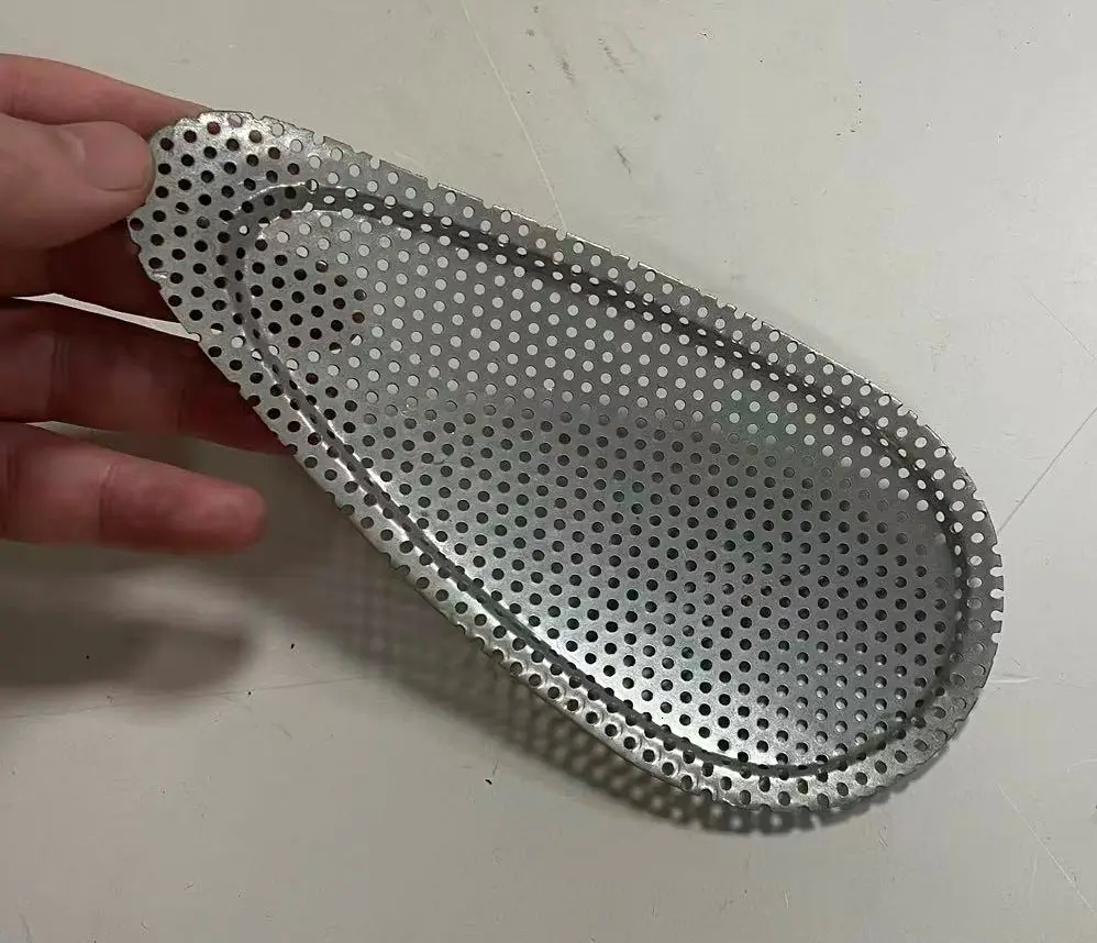
Real Production Perspective: Dense Piercing in a Metal Knee-Guard Component
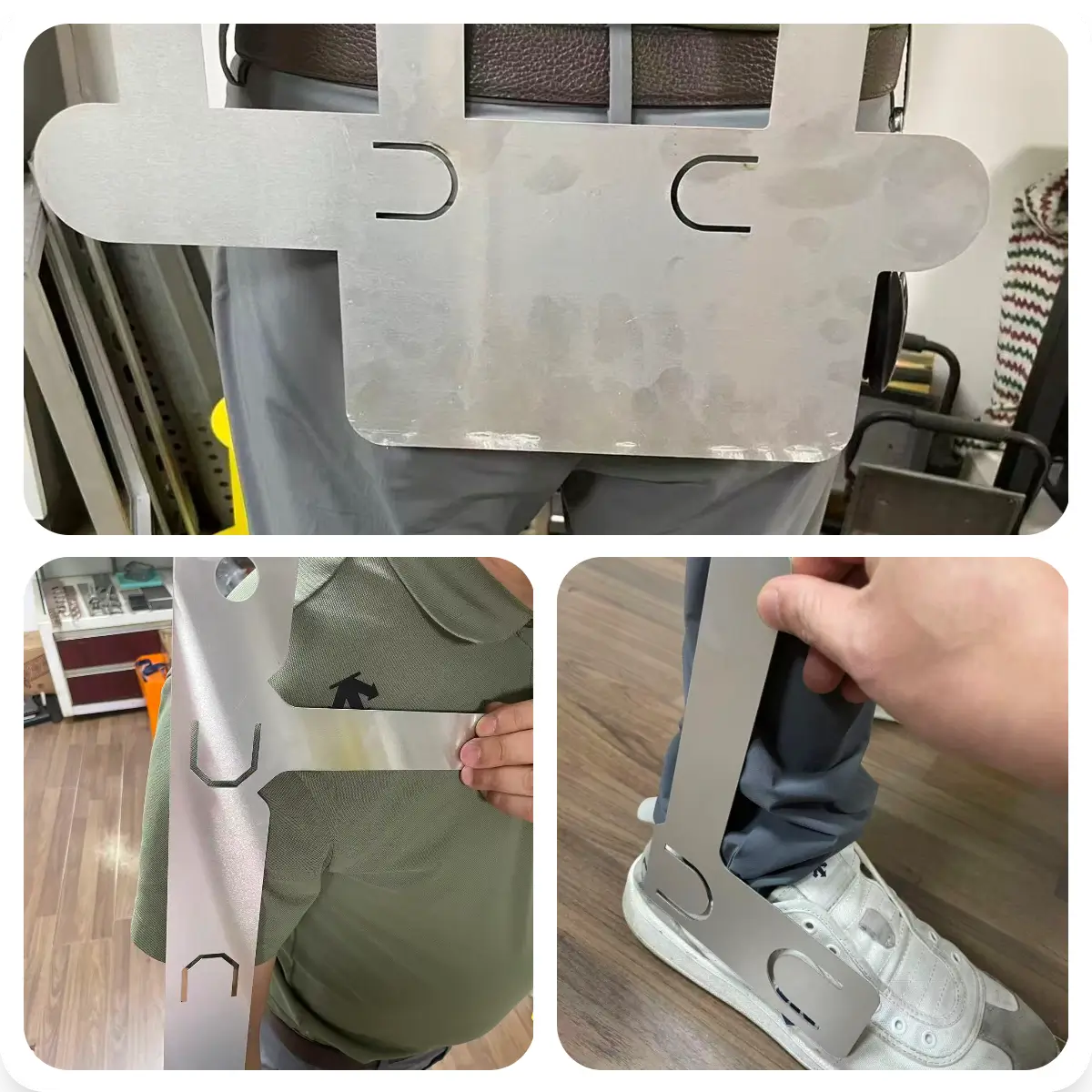
In one Metal Stamp Factory project, a steel knee-guard component for equestrian protective equipment required a dense pattern of small pierced holes across most of the part surface. After piercing, the component was also formed into a curved profile to fit the protective structure. The steel part was subsequently sent to a qualified external partner facility for galvanizing. The finished guard also incorporated plastic or foam components.
The manufacturing challenge was not limited to creating the large number of holes. Each piercing operation also generated a small scrap slug, so reliable slug release and scrap evacuation were important to production efficiency. If small slugs remained in the hole area, became trapped around the tooling, or failed to evacuate consistently, the process could require additional stopping, cleaning, or manual correction.
For this type of densely perforated part, die design and process tuning play an important role in keeping scrap movement stable. Punch condition, die-side retention, slug release, scrap paths, and setup consistency all need to work together so that the large number of small slugs can leave the tooling area without interfering with continued production.
This example does not prove that dense piercing automatically causes slug pulling. Broader metal stamping design guidelines can help frame manufacturability considerations for pierced features, while this case focuses specifically on slug control and scrap evacuation. It shows why parts with many closely spaced pierced holes can place greater practical demands on slug control and scrap evacuation, making tooling design and press-room adjustment especially important for stable production.
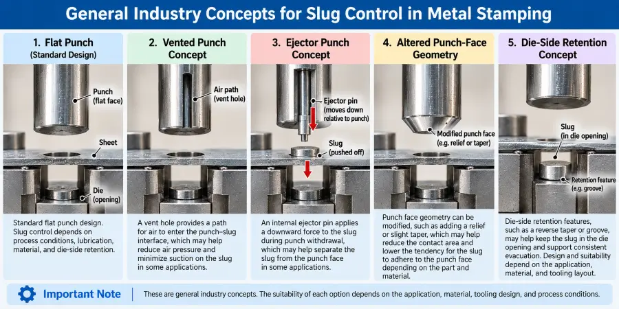
General Industry Solutions for Slug Pulling
In sheet metal stamping operations, several industry concepts are utilized to address scrap behavior. General industry options may include:
Reduce Punch-Side Adhesion
To reduce the tendency of scrap to lift with the punch, general industry options include:
- Vented Punch Concepts: Vented punches can provide a path for air to enter the interface and may reduce punch-face suction in suitable tooling designs.
- Altered Punch-Face Geometry: Modifying punch tips with small shear angles, rooftops, or contoured profiles can reduce flat contact area and may reduce adhesion in some applications.
- Ejector Punch Concepts: Some tooling designs use an internal ejector pin to apply a downward force to the slug during punch withdrawal.
Improve Die-Side Slug Retention
To enhance how the die matrix holds the scrap, general industry approaches include:
- Reverse Taper Dies: Reverse taper or engineered retention features are examples of tooling concepts used in some applications to increase resistance to upward slug movement.
- Retention Grooves: Engineered grooves or slots are examples of die-side retention concepts used in some applications to increase resistance to upward slug movement.
- Die Land Surface Condition: Die land surface condition can influence friction and slug retention behavior and should be reviewed as part of troubleshooting.
Review Lubricant Conditions
- Excessive or inconsistent lubricant application may increase punch-side adhesion in some piercing conditions.
- Reviewing application methods, fluid volume, or lubricant selection can help manage surface-tension effects.
Review Punch and Die Condition
- Review punch and die condition after maintenance or sharpening, including any change that could affect slug attraction or retention.
- Review cutting-edge condition only as it relates to changes in slug behavior or retention.
Review Scrap Evacuation
- Review the scrap path and any existing evacuation method to confirm that loose scrap can leave the die area without obstruction.
How to Prevent Slug Pulling
Reducing the risk of slug-pulling and scrap-control problems involves reviewing both tooling condition and setup factors:
Diagnose the Mechanism Before Modifying Tooling
Avoid making permanent alterations to punches or die components until the primary contributors (adhesion vs. retention) are evaluated. Modifying tooling prematurely may introduce secondary issues, such as altered burr height or accelerated tool wear.
Maintain Consistent Punch and Die Conditions
Review punch and die condition after maintenance or sharpening, including any change that could affect slug attraction or retention.
Control Lubricant Application
Excessive or inconsistent lubricant application may increase punch-side adhesion in some piercing conditions. Regulating application consistency helps maintain steady surface conditions on the strip.
Review Slug Retention Where Needed
Evaluate whether specific piercing stations require engineered retention features or punch-face modifications based on part geometry, material type, and past tooling performance.
Verify Scrap Evacuation
Review the scrap path and any existing evacuation method to confirm that loose scrap can leave the die area without obstruction.
Avoid Universal Tooling Rules
Fixed clearance percentages, retention geometries, or punch-face solutions should not be applied universally across different materials, thicknesses, and die designs. Process conditions must be evaluated for each specific application.
What OEM Buyers Should Ask When Slug Pulling Occurs
When discussing scrap control or part surface issues with a supplier, OEM buyers can use these 7 questions to clarify the evaluation:
- Where is the pulled slug being found?
- Purpose: Helps narrow the investigation between punch-side adhesion and die-side retention factors.
- Does the slug remain attached to the punch tip during inspection?
- Purpose: Helps evaluate whether punch-face interaction, such as surface tension or suction, may be contributing to upward scrap movement.
- Is the problem intermittent or repeatable across production runs?
- Purpose: Helps compare whether variable process factors or recurring tooling and setup conditions should receive more attention during the investigation.
- Did the issue begin after tool sharpening or setup changes?
- Purpose: Identifies whether recent maintenance or setup adjustments changed punch or die land conditions.
- Have lubricant conditions or application methods changed?
- Purpose: Helps determine whether lubricant-related interface conditions changed when the slug-pulling issue appeared.
- Is the issue isolated to a specific piercing station?
- Purpose: Helps compare punch-side and die-side factors at the individual station level.
- How was the corrective action verified before resuming production?
- Purpose: Confirms that corrective steps were verified through appropriate metal stamping quality inspection checks, trial runs, and scrap review before production resumed.
Frequently Asked Questions
1. What causes slug pulling in metal stamping?
Slug pulling can occur when punch-side adhesion or attraction becomes strong enough relative to die-side retention for a pierced slug to travel upward with the punch.
2. Why does a slug stick to the punch during piercing?
A slug can stick to the punch tip due to fluid film adhesion from lubricants, pressure differentials created between flat surfaces, or magnetic attraction following maintenance.
3. What is the difference between slug pulling, slug stacking, and slug jamming?
Slug pulling involves a slug returning upward with the punch toward the strip area. Slug stacking occurs when multiple slugs accumulate in the die path without evacuating. Slug jamming happens when a single slug becomes tilted or wedged within the die opening.
4. Can punch-to-die clearance affect slug pulling?
Yes. Punch-to-die clearance can influence how the slug deforms and interacts with the die opening. Depending on the material, thickness, and tooling geometry, clearance may affect slug retention behavior, but it should not be treated as a universal single cause of slug pulling.
5. How can slug pulling be prevented in stamping dies?
The risk of slug pulling can often be reduced by first identifying whether punch-side adhesion, die-side retention, lubricant conditions, tooling condition, or scrap evacuation is contributing to the problem. General industry options may include vented or ejector punch concepts and engineered retention features where appropriate.
About Metal Stamp Factory
Metal Stamp Factory was established in 2014 in Xiamen, China, focusing on custom metal stamping, tooling development, and precision hardware manufacturing for OEM projects.
When reviewing slug-pulling or piercing issues, our approach is to compare punch condition, die condition, slug behavior, lubricant conditions, scrap evacuation, and setup factors before deciding on corrective action.