Written by Shengtong Chen
Founder of Metal Stamp Factory with more than 25 years of hands-on experience in tooling development, metal stamping, and OEM production.
In sheet metal stamping operations, cracking and tearing represent physical breaches in a part’s structural integrity. Whether appearing as a microscopic split along a bend line or a tear across a drawn sidewall, material fracture indicates that the local deformation demand exceeded the sheet metal’s forming capability under those specific process conditions.
A foundational principle of root-cause analysis in metal forming is that a crack location is a diagnostic clue, not proof of a single root cause.
Cracking and tearing occur when deformation becomes too concentrated for the local material condition and chosen forming path. When a blank undergoes bending, stretching, or deep drawing, the sheet must flow and deform to match the contour of the die. If local tensile strain exceeds the material’s ability to accommodate further plastic deformation, the sheet begins to thin locally and may eventually fracture.
Resolving cracking in sheet metal stamping requires a methodical diagnostic approach rather than immediate trial-and-error tooling modifications. When a failure occurs, manufacturing engineers and quality teams should systematically review:
- Material Condition: Mechanical properties, supply condition, temper, elongation behavior, and batch-to-batch consistency.
- Part and Tooling Geometry: Radii, transition zones, feature spacing, and local strain concentration areas.
- Material Flow and Restraint: Blank holding conditions, draw-bead geometry, restraint level, and material feed.
- Friction and Lubrication: Lubricant coverage, tool surface condition, and contact conditions.
- Process and Setup Parameters: Press shut height, die clearance, edge preparation, and forming sequence.
While broader common metal stamping defects such as minor surface marks can sometimes be managed through small adjustments, cracking can compromise part integrity or functionality and therefore requires root-cause evaluation. Understanding the underlying mechanics of material failure helps teams establish stable, repeatable forming processes.
What Are Cracking and Tearing in Sheet Metal Stamping?
In precision sheet metal stamping, terms such as cracking, tearing, and splitting are frequently used on the shop floor to describe open fractures. While they all refer to material separation, they can reflect different stress conditions and material responses during the forming process.
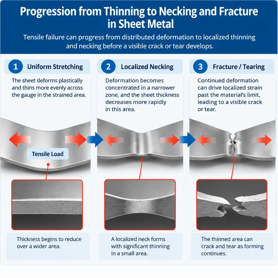
Localized Thinning and Necking Before Fracture
In ductile sheet metals, tensile fracture typically follows a sequence of plastic deformation:
- Uniform Stretching: As the tool engages the blank, the metal deforms plastically across the unconstrained zone. During this stage, work-hardening helps distribute deformation across surrounding areas.
- Deformation Localization: If applied stress continues to increase beyond the material’s work-hardening capacity for that geometry, deformation stops spreading evenly and begins concentrating within a localized zone.
- Local Thinning and Necking: As strain concentrates, the local thickness of the sheet within that zone decreases rapidly. Once localized necking initiates, subsequent deformation concentrates heavily within this thinned region.
- Tensile Fracture: Continued forming stroke travel can drive localized strain past the material’s limit, leading to a visible split or tear.
Measuring wall thickness adjacent to a failure site offers useful diagnostic information. Significant localized thinning near the fracture often points toward excessive tensile stretching as a key factor.
Cracking, Tearing, Splitting, and Fracture
In production communications, these terms describe related failure modes:
- Tensile Splitting / Tearing: Frequently describes fractures associated with high tensile strain during stretching or drawing. Tearing commonly occurs across unsupported spans, drawn sidewalls, or near punch radii where material movement has been restricted.
- Brittle Fracture: Observed in materials with reduced ductility or harder tempers where plastic deformation capacity is limited, resulting in sharp fracture lines with minimal prior necking.
Edge Cracking Is a Different Diagnostic Pattern
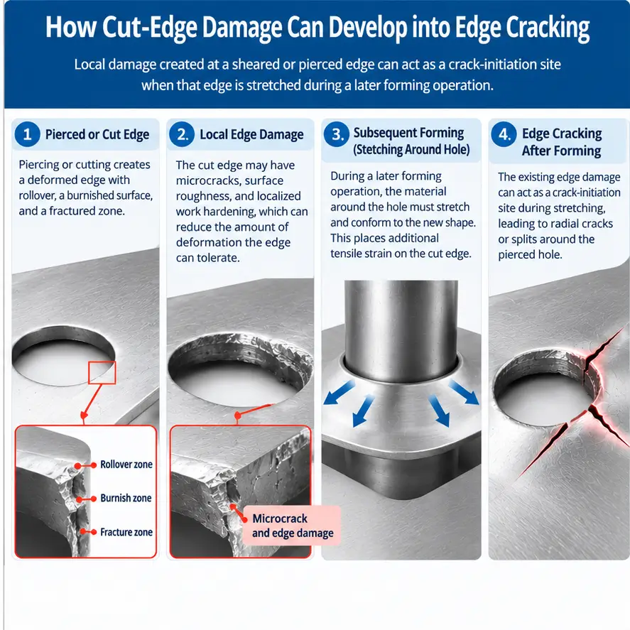
Cracks that originate along a cut, sheared, pierced, or trimmed edge present a distinct diagnostic pattern compared to cracks occurring in the middle of a continuous panel.
When a blank is pierced or trimmed, the shearing action creates a localized deformation zone along the perimeter. This cut edge experiences shear strain, leaving a band of material with local work hardening and potential edge damage.
If a subsequent forming step—such as stretch flanging or hole expanding—stretches this cut edge, the local edge formability can be substantially lower than the global material ductility. Micro-damage or burrs along the edge can act as stress raisers, initiating edge cracks under lower overall strain levels than would otherwise be required to split the continuous sheet.
Main Causes of Cracking and Tearing
Preventing cracking in sheet metal stamping requires evaluating how material properties, part features, tooling geometry, and contact conditions interact during forming.
Material Ductility, Temper, and Formability
The mechanical properties of incoming sheet stock influence how much deformation the material can absorb before necking:
- Ductility and Elongation: Lower overall elongation capability reduces the material’s capacity to stretch over die contours.
- Material Temper and Strength: Harder or more heavily cold-worked material conditions may provide less available forming ductility than softer conditions, depending on the alloy and required deformation. This can increase cracking risk in demanding bending or stretching operations.
- Batch-to-Batch Variation: Lot-to-lot variations in thickness, temper, or grain structure can cause a process that ran successfully on one batch to exhibit cracking on another.
Excessive Localized Strain
Broader metal stamping design guidelines help explain how geometry influences stress distribution across a part. Sharp transitions can concentrate strain in small areas:
- Proximity to Holes and Cutouts: Piercing a feature too close to a bend line or drawn zone leaves a narrow strip of metal that bears disproportionate strain.
- Notches and Corners: Sharp internal cutouts or tight corner transitions concentrate applied loads, creating localized stress raisers.
- Abrupt Transitions: Sharp changes in profile width or forming depth force material to stretch unevenly across short distances.
Tight Punch, Die, Bend, or Draw Radii
Tooling radii strongly affect local strain severity:
- Tight Punch Radii: A small punch radius concentrates contact stress and localized stretching into the material directly beneath the tool tip.
- Tight Die Entry Radii: In drawing or stretching, small die entry radii increase resistance to material movement, forcing the sheet to stretch more over the punch.
- Tight Bend Radii: Formed bend radii that are small relative to sheet thickness increase tensile strain on the outer surface of the bend.
Restricted Material Flow and Excessive Restraint
In drawing and stretch-forming operations, material must move inward from the outer flange to supply the zone being shaped by the punch:
- Excessive Blank Restraint: High clamping force or restrictive binder conditions can prevent material from sliding into the die cavity, forcing the part to form primarily through stretching.
- Aggressive Draw Beads: Deep or sharp draw bead geometry increases restraint, which can restrict material flow and increase local strain in downstream drawn areas.
- Inadequate Clearance: Insufficient clearance between punch and die can pinch the sheet, increasing drag and local stress.
Friction and Lubrication Conditions
Contact conditions affect material sliding and local strain distribution:
- High Surface Friction: Dry or poorly lubricated tool surfaces increase friction at tool contact zones, restricting material movement across punch and die radii and concentrating strain in adjacent unsupported zones.
- Lubrication Changes: Insufficient or inconsistent lubrication can increase local friction. In some forming conditions, metal pickup or galling may further increase drag and contribute to localized tearing.
Edge Condition and Previous Cutting Operations
The condition of cut edges from upstream blanking or piercing operations influences formability:
- Local Work Hardening: Shear forces from cutting operations leave a work-hardened zone along the edge.
- Burrs and Micro-Damage: Rough edges, burrs, or micro-cracks act as local initiation sites when the edge is subsequently flanged or stretched.
For background on how burrs develop during cutting, see our guide to stamping burr formation.
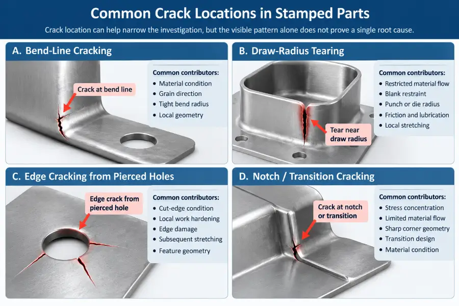
Where Cracks Appear Can Help Narrow the Cause
The location and orientation of a crack offer diagnostic clues for evaluating potential contributing factors.
Cracks at Bend Lines or Formed Radii
- Observed Pattern: Splits running along the outer curvature of a bend line or formed radius.
- Potential Contributors: Material condition, grain direction relative to the bend axis, tight tooling radius, or severe local geometry.
- What to Review: Review material temper, bend orientation relative to rolling direction, punch nose radius, and part geometry.
Tears Near Punch Corners or Draw Radii
- Observed Pattern: Curved splits or tears along drawn sidewalls, punch nose transitions, or bottom corners.
- Potential Contributors: Restricted material flow, excessive blank restraint, tight tool radii, or high friction.
- What to Review: Review blank restraint settings, draw-bead condition, lubrication coverage, and punch or die entry radii.
Cracks Around Pierced Holes and Cut Edges
- Observed Pattern: Radial splits extending outward from the edge of a pierced hole, cutout, or trimmed flange.
- Potential Contributors: Cut-edge condition, local work hardening from piercing, tight feature spacing, or severe edge stretching.
- What to Review: Inspect cut-edge quality, check piercing tool sharpness and clearance, evaluate local stretch severity, and review feature spacing.
Cracks Near Notches, Corners, and Geometry Transitions
- Observed Pattern: Localized cracking initiating at internal corner cutouts or abrupt contour changes.
- Potential Contributors: Strain concentration, sharp transition geometry, or restricted local material movement.
- What to Review: Review internal radii, cut-edge quality at the notch, and transition geometry.
Cracking During Deep Drawing
Deep drawing involves a combination of tension, compression, and material movement. As the punch drives material into a die cavity, the outer blank in the flange is pulled inward while the sidewall experiences tensile loads.
For broader engineering background on drawing and stretching behavior, see AHSS Insights on sheet metal forming modes.
Why Restricted Material Flow Can Lead to Tearing
For a drawn shape to form successfully, material in the outer flange must slide inward toward the die cavity. As flange material moves inward, it undergoes circumferential compression.
If material movement in the flange is overly restricted, the displacement must be accommodated primarily by stretching the metal in the sidewall zone. When local tensile stress exceeds the material’s capability in that thinned wall area, tearing can occur, often near the transition to the punch radius.
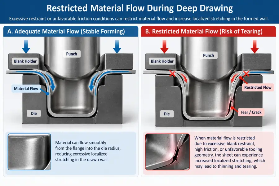
Blank Holding and Draw-Bead Restraint
The blank holder regulates material entry into the die cavity:
- Higher Restraint: Restricting flange movement increases the proportion of stretch relative to draw, which can elevate local tensile strain in the sidewalls.
- Uneven Restraint: Non-uniform pressure across the blank holder or variable draw-bead engagement can cause material to draw unevenly, concentrating strain in specific zones.
The Relationship Between Tearing and Wrinkling
In drawing operations, tearing and wrinkling represent related process boundaries:
- Increasing restraint may reduce wrinkling in sheet metal stamping in some forming conditions, but excessive restraint can restrict material flow and increase the risk of localized thinning or tearing.
Managing these competing risks requires balancing binder restraint, tool radii, and lubrication for the specific part geometry.
Real Production Perspective: Material Condition Can Decide Whether a Part Survives Forming
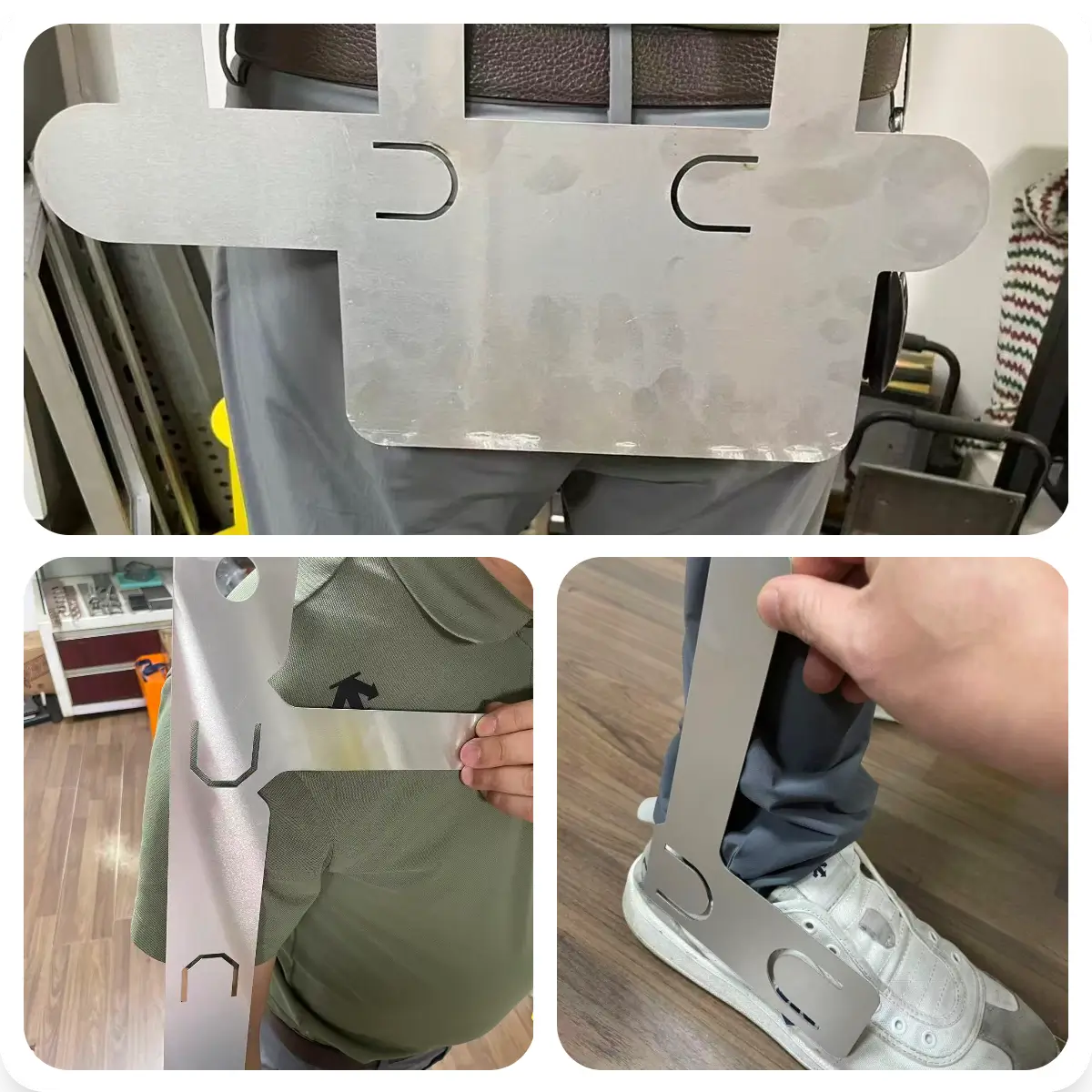
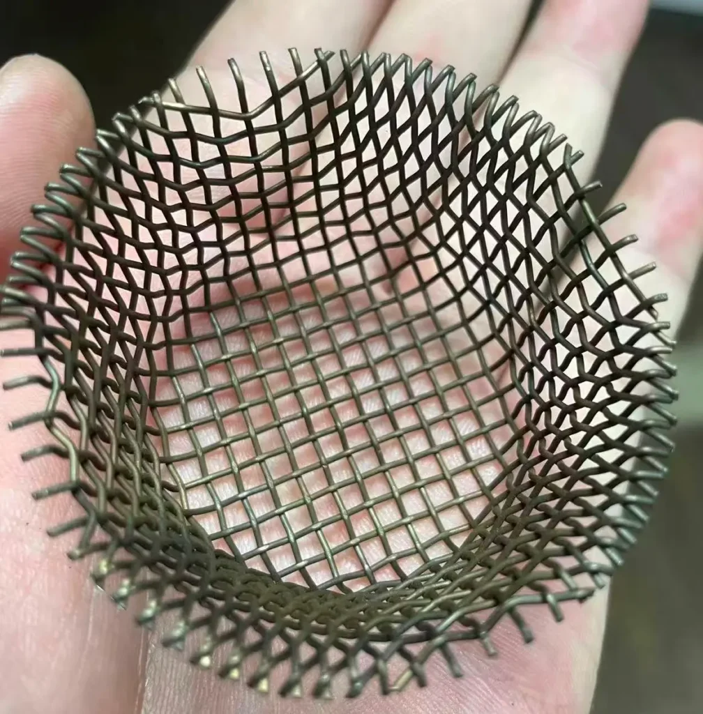
In one Metal Stamp Factory project, a formed component was produced from 304 stainless steel mesh. The geometry required the mesh to undergo substantial stretching during forming.
When the mesh was used in a non-annealed condition, it did not have sufficient formability for the required deformation and was prone to cracking and tearing during the stamping and stretching operation.
For this specific part, the 304 stainless steel mesh was annealed through a qualified external processing partner before forming. After annealing, the surface had a noticeably darker, blackened appearance. This color change was an observed condition after annealing and was not used by itself as proof of material quality or annealing condition.
The annealed material provided the forming behavior needed for this particular geometry and allowed the mesh to undergo the required stretching without the cracking and tearing seen with the non-annealed material.
This example illustrates why alloy designation alone does not fully describe forming behavior. Material condition, required deformation, geometry, tooling, and process conditions need to be considered together when troubleshooting cracking in stamped parts.
How to Troubleshoot Cracking and Tearing
When cracking or tearing occurs during production or tool trials, diagnostic efforts should be structured logically. Remember: A crack location is a diagnostic clue, not proof of a single root cause.
The following diagnostic table outlines common observed patterns, potential contributing factors, and areas to review:
| Observed Pattern | Possible Contributors | What to Review |
|---|---|---|
| Crack along bend line | • Material condition or temper • Grain direction orientation • Tight punch radius • Local part geometry | • Material condition and documentation • Bend orientation relative to grain direction • Tooling radius and surface condition • Bend geometry |
| Tear near draw radius | • Restricted material flow • Excessive blank restraint • Friction or lubrication breakdown • Tight die or punch radius | • Blank restraint setup • Draw-bead condition and engagement • Lubricant selection and coverage • Punch and die entry radii |
| Edge crack from pierced hole | • Cut-edge condition or micro-damage • Local work hardening from cutting • High edge-stretch requirement • Feature geometry proximity | • Pierced edge condition and burr presence • Piercing clearance and tool condition • Stretch severity along the edge • Distance between hole and forming zone |
| Crack after material batch change | • Material property or thickness variation • Surface finish variation affecting friction • Changed material temper or condition | • Available material documentation • Sheet thickness and condition • Surface condition and cleanliness • Process setup parameters |
| Crack after tooling/setup change | • Changed contact or restraint conditions • Altered shut height or clearance • Surface friction changes after maintenance • Tooling seating or alignment shift | • Recent tooling and setup modifications • Forming sequence and clearances • Tooling surface polish and alignment • Lubrication setup consistency |
| Intermittent tearing | • Variations in material condition • Lubrication application inconsistency • Setup or clamping variation • Tooling wear or localized galling | • Material property consistency across lot • Lubrication application coverage • Setup stability and consistency • Tool radii surfaces for metal pickup |
How to Prevent Cracking and Tearing
Preventing material fracture requires addressing strain concentration and material flow during process design and tooling development.
Reduce Localized Strain Concentration
- Incorporate Smooth Transitions: Avoid sharp internal corners, notches, or abrupt steps in part geometry where practical.
- Maintain Feature Spacing: Ensure pierced features and cutouts are placed with adequate spacing from primary forming or bending zones.
Improve Material Flow
- Review Die Entry Radii: Ensure die entry radii in drawing areas are sized to allow smooth material movement into the cavity.
- Maintain Tool Surface Finish: Keep contact surfaces on punches, dies, and binders clean, polished, and free of scoring to reduce localized drag.
Review Tool Radii and Forming Geometry
- Match Radii to Application: Select tooling radii that suit the material grade, thickness, and forming severity.
- Consider Grain Orientation: Where part layout permits, consider how bend lines align with the rolling direction of the sheet.
Control Blank Restraint
- Adjust Blank Restraint: Set binder pressure to a level that manages wrinkling while permitting necessary material movement for the given geometry.
- Balance Restraint Features: Position and size draw beads to achieve balanced restraint across complex forming zones.
Maintain Consistent Lubrication and Contact Conditions
- Select Suitable Lubricants: Choose lubricants designed for the specific forming severity and material type.
- Ensure Uniform Coverage: Apply lubricant consistently across contact surfaces to maintain steady friction conditions.
Review Cut Edges Before Subsequent Forming
- Maintain Cutting Tool Sharpness: Keep blanking and piercing tools sharp to minimize edge damage, excessive rollover, or heavy burrs.
- Maintain Proper Clearances: Set cutting clearances correctly for the material type and thickness to support clean edge shear.
Control Material Consistency
- Establish Clear Material Specifications: Define required material specifications, including temper and acceptable thickness ranges.
- Review Material Documentation: Verify incoming material documentation to confirm compliance with project requirements.
Real Production Perspective: Diagnose Before Modifying the Tool
When cracking occurs during a production run, the immediate reaction may be to modify the die by enlarging clearances or grinding larger radii. However, making permanent tool changes without verification risks introducing secondary issues.
A conservative diagnostic evaluation involves comparing key process factors:
- Material Condition: Check incoming material thickness, condition, and documentation against established standards.
- Part and Crack Characteristics: Inspect the crack location, orientation, and surrounding sheet thickness to determine whether localized thinning or edge damage is present.
- Tooling and Setup Condition: Review press setup parameters, shut height, lubrication coverage, and tooling contact surfaces for signs of galling or wear.
- Forming Sequence: Confirm that multi-stage operations are performing as intended without unexpected pre-straining.
By systematically evaluating these areas, engineering teams can determine whether the root cause is primarily material-related, geometry-related, tooling-related, or process-related, allowing for targeted adjustments without unnecessary tool modifications.
Advanced Engineering Background: Forming Limits and Local Formability
In manufacturing engineering, analytical concepts are sometimes used to evaluate material deformation during forming:
- Forming Limit Diagrams: Engineering tools used to understand combinations of strain where localized necking may initiate under continuous panel stretching.
- Major and Minor Strain: Terms that describe primary and secondary deformation directions in the plane of the sheet during forming.
- Local Edge Formability: Cut edges behave differently from continuous sheet panels. Cut-edge damage, work hardening, or burrs can reduce local edge formability, leading to edge cracking at lower overall strain levels than predicted for continuous sheet metal.
These engineering concepts provide general context for understanding material behavior on the factory floor.
What OEM Buyers Should Ask When Stamped Parts Start Cracking
When cracking or tearing issues arise during part development or production, clear communication between OEM buyers and their stamping supplier helps isolate the cause:
- Did the failure coincide with a new material batch or coil lot?
- Purpose: Helps identify if material property or thickness variations are contributing.
- Is the crack consistently located in the exact same position on every part?
- Purpose: A fixed location often suggests a geometric feature or tooling contact point, while variable locations may indicate material or lubrication inconsistency.
- Does the crack originate from a cut, pierced, or trimmed edge?
- Purpose: Helps distinguish between local edge formability issues and global stretch limitations.
- Have any recent adjustments been made to tooling, setup, or press parameters?
- Purpose: Identifies whether recent maintenance or operational shifts changed forming conditions.
- Has the lubricant type or application coverage changed?
- Purpose: Uncovers shifts in surface friction that could affect material sliding.
- At which specific operation or station does the defect first appear?
- Purpose: Focuses troubleshooting on the precise forming step responsible for the issue.
- How was the corrective action verified on replacement parts?
- Purpose: Ensures that the remedy was confirmed through metal stamping quality inspection
on sample parts before resuming production.
- Purpose: Ensures that the remedy was confirmed through metal stamping quality inspection
Frequently Asked Questions
1. What causes cracking in sheet metal stamping?
Cracking occurs when localized tensile or shear strain exceeds the material’s deformation capability under specific forming conditions. Contributing factors can include material temper or ductility limits, tight tooling radii, excessive blank restraint restricting material movement, sharp part geometry, insufficient lubrication, or damaged cut edges that act as stress raisers.
2. Why does sheet metal tear during deep drawing?
Sheet metal can tear during deep drawing when localized tensile deformation in the drawn wall exceeds the material’s forming capability under those conditions. This often occurs when excessive blank holder force or restrictive draw beads prevent the outer flange from sliding inward into the die cavity, forcing the part to form primarily through stretching.
3. Why do cracks form around pierced holes or cut edges?
Cracks can form around pierced holes or cut edges because the cutting operation may leave a localized zone of work hardening, burrs, or micro-damage along the perimeter. When a subsequent forming step stretches this edge, the local edge condition may reduce the amount of deformation it can tolerate compared with an undamaged continuous area of the sheet, increasing the risk of splitting.
4. Can excessive blank holding cause sheet metal tearing?
Yes. Excessive blank restraint can restrict material movement from the outer flange into the die cavity. When insufficient material can draw inward, localized stretching and thinning may increase, raising the risk of tearing in wall or radius sections.
5. How can cracking and tearing be prevented in metal stamping?
The risk of cracking and tearing can often be reduced by using appropriate tooling radii, managing blank restraint to allow necessary material flow, selecting material conditions suitable for the required forming severity, controlling cut-edge condition, maintaining consistent lubrication, and avoiding abrupt geometric transitions.
About Metal Stamp Factory
Metal Stamp Factory was established in 2014 in Xiamen, China, focusing on custom metal stamping, tooling development, and precision hardware manufacturing for OEM projects.
When reviewing cracking or tearing in stamped parts, our approach is to compare material condition, part geometry, tooling condition, material flow, lubrication, and process setup before deciding whether the issue calls for a material, tooling, or process adjustment.