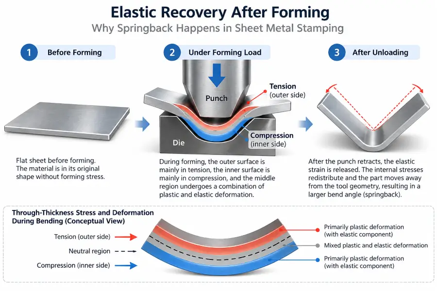
Metal stamping springback is the elastic recovery that occurs after forming pressure is removed and a stamped part is released from the tooling. During forming, part of the material undergoes permanent plastic deformation while another portion retains recoverable elastic strain. Once the punch retracts and the part is no longer constrained by the die, those internal stresses redistribute and the part may move away from its closed-tool geometry.
For OEM buyers, manufacturing engineers, and sourcing managers, springback in metal stamping can appear as an opened bend angle, a changed bend radius, curved sidewalls, or broader geometry shifts. It is one of the common metal stamping defects that requires the material, part geometry, tooling, and process conditions to be reviewed together rather than assuming that one visible pattern proves a single cause.
This article explains the physical causes of springback, the factors that influence it, how to troubleshoot changing springback behavior, and the important difference between reducing springback and compensating for it.
What Is Metal Stamping Springback?
Elastic Recovery After Forming
To understand elastic recovery in sheet metal, it helps to look at what happens through the material thickness during bending or forming.
As a sheet bends, material on the outside of the bend is placed primarily in tension, while material on the inside is placed primarily in compression. Stress and strain vary continuously through the sheet thickness. Portions of the section undergo permanent plastic deformation, while other portions retain elastic strain that can recover after the forming load is removed.
When the tooling retracts, the part is no longer constrained to the exact shape of the punch and die. Recoverable elastic strain is released, and the internal stress distribution moves toward a new equilibrium.
The resulting free-state geometry may therefore differ from the geometry of the part while it was still under forming load. This change is commonly described as springback.
How Springback Appears in Stamped Parts
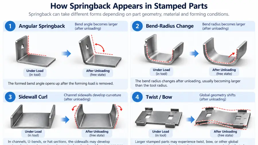
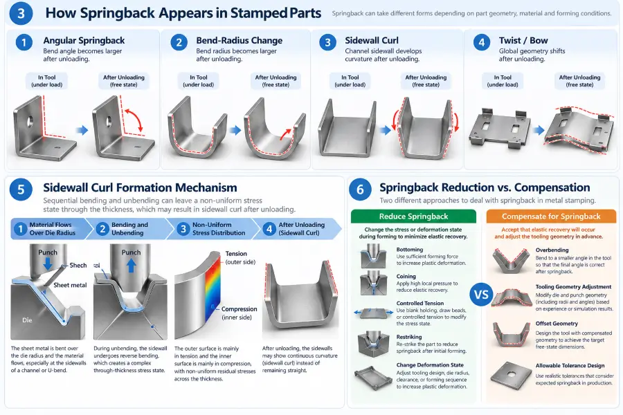
Springback does not appear only as a simple bend opening. Depending on the part geometry, material flow, and forming sequence, several forms of geometric change may occur.
- Angular springback: A formed flange or wall changes angle after unloading. The change is often described as the bend opening, although the exact direction and magnitude depend on the forming condition.
- Bend-radius change: The radius of a formed feature changes after the tooling releases the material.
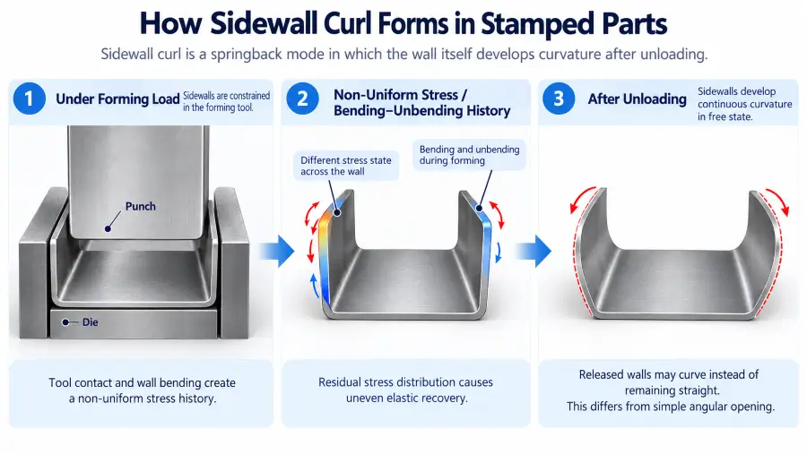
- Sidewall curl: In channels, U-shaped sections, hat sections, and similar formed profiles, the wall itself develops curvature because of the bending and unbending stress history created during material flow.
- Twist, bow, or global geometry shift: More complex stamped parts may move out of plane when internal stresses are not distributed uniformly across the part.
For this reason, identifying the type and location of the geometry change is an important first step in springback troubleshooting.
What Causes Springback in Sheet Metal?
Sheet metal springback causes usually fall into four interacting groups:
- Material properties: Yield strength, elastic modulus, temper, work-hardening behavior, and anisotropy affect how much elastic strain remains after forming.
- Part geometry: Sheet thickness, bend radius, flange geometry, channels, and other formed features influence stress distribution through the material.
- Tooling and forming method: Punch and die geometry, tool contact, forming depth, bottoming, coining, restriking, and similar process choices affect the balance between elastic and plastic deformation.
- Setup and process conditions: Tool seating, blank restraint, lubrication, forming sequence, support conditions, and process consistency can change how the material flows and recovers.
These factors should be evaluated together. Springback rarely has a useful one-variable explanation in a production part.
Material Factors That Influence Springback
Yield Strength and Elastic Modulus
The relationship between a material’s yield strength and its Young’s modulus or elastic modulus—often evaluated through the yield-to-modulus ratio—is a primary factor influencing springback behavior. Technical references on springback in sheet metal forming describe elastic recovery as a function of material behavior together with the forming and geometry conditions.
Yield strength defines the stress level at which permanent plastic deformation begins, while elastic modulus describes how strongly the material resists elastic deformation. When yield strength is relatively high compared with elastic modulus, the potential for elastic recovery after unloading generally increases.
Higher-strength sheet materials often show greater springback tendency than lower-strength materials under comparable forming conditions, although the actual response also depends on thickness, temper, geometry, and forming method.
Strain Hardening and Material Temper
As sheet metal deforms during stamping, strain hardening can increase the material’s flow stress in heavily worked regions. This changes the stress state present at the end of the forming stroke and can affect how the part recovers after unloading.
Annealed and work-hardened conditions of the same alloy can respond differently because temper changes yield behavior and strain-hardening response. For this reason, springback should not be judged from the material family alone.
Sheet Thickness
Sheet thickness affects how strain is distributed through the material during forming. Its effect should be considered together with bend radius, material strength, temper, and the forming method.
A relatively thin sheet formed over a wide radius may retain a larger proportion of elastically recoverable deformation than a different thickness and radius combination. This is why thickness alone should not be used as a universal predictor of springback.
Grain Direction and Anisotropy
Rolling during coil production can create directional differences in mechanical behavior, commonly described as anisotropy. The material can respond differently depending on the orientation of the bend or formed feature relative to the rolling direction.
These directional effects may influence elastic recovery and final free-state geometry, particularly when a part contains multiple bends or features oriented in different directions.
Material Choice Depends on the Part Function
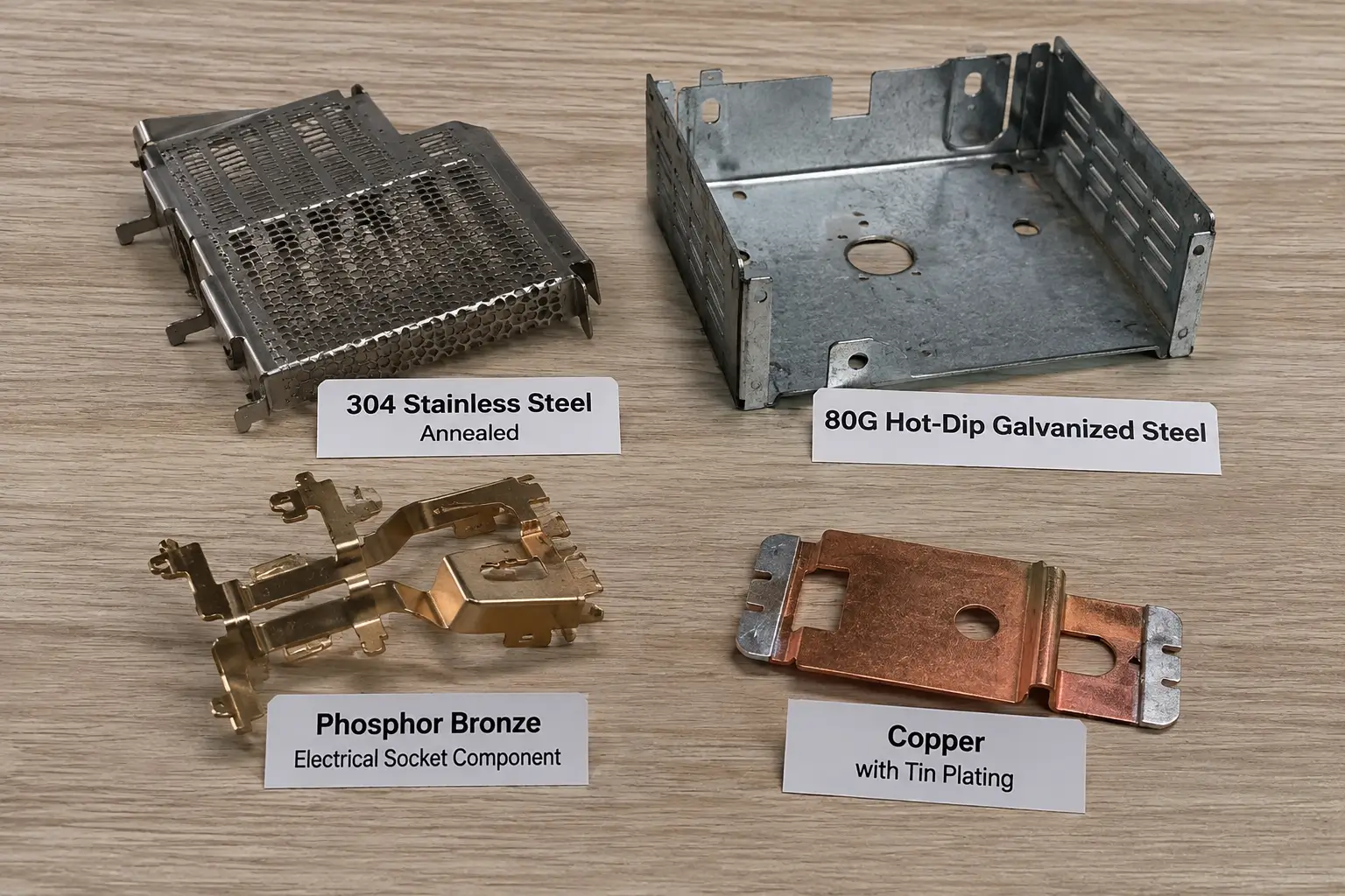
In OEM stamping projects, the material is usually selected first according to the functional requirements of the finished part rather than springback alone. Broader material and geometry decisions should be reviewed together with the metal stamping design guidelines for the part.
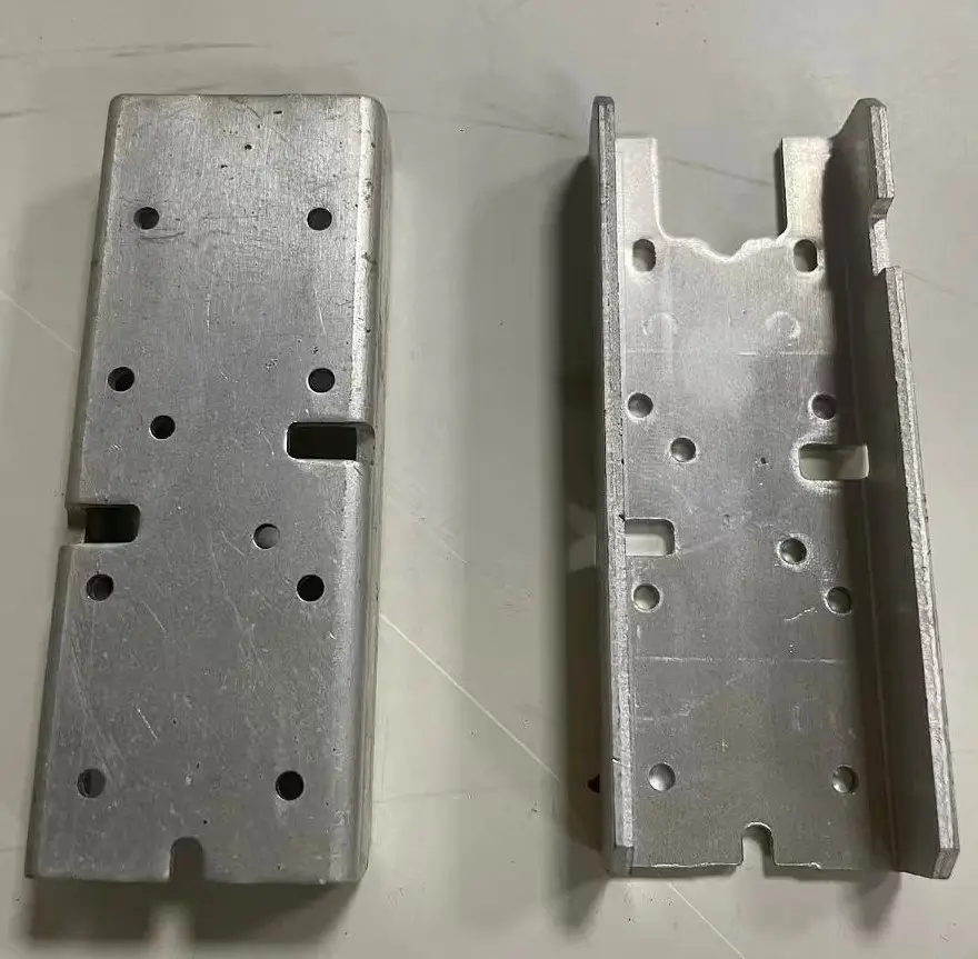
Aluminum may be chosen for applications where low weight, corrosion resistance, electrical conductivity, or heat-dissipation performance is important. It is common in electronic stamped components, formed housings, brackets, and heat-dissipation parts. However, aluminum should not be described as a material that simply “does not spring back.” Its actual springback behavior depends on the specific alloy, temper, thickness, geometry, and forming conditions.
Likewise, aluminum does not provide the same stiffness or strength as every steel option for every application. Parts that require greater structural rigidity, load-bearing capability, or resistance to deformation may require a different material grade, thickness, or design approach.
The practical point is that material selection and springback control are related, but they are not the same engineering decision.
Geometry Factors That Affect Springback
Bend Radius and R/t Relationship
The ratio of the inside bend radius to sheet thickness, commonly described as the radius-to-thickness ratio (R/t), is an important geometric factor influencing elastic recovery.
When the R/t ratio is relatively high, such as when a comparatively large radius is formed in relatively thin material, the strain through the sheet thickness is lower and a greater proportion of the deformation may remain elastically recoverable.
A lower R/t ratio can increase plastic deformation through a larger portion of the section and may reduce relative springback under otherwise comparable conditions. However, the actual result still depends on the material and forming method, so R/t should not be treated as a universal threshold.
Bend Angle and Flange Geometry
Bend angle and flange geometry influence how a small angular change is expressed in the finished part. A minor change at the bend line can become a larger positional shift at the end of a long flange.
For this reason, the same amount of elastic recovery may have very different practical effects on two parts with different flange lengths or geometry.
Channels, U-Bends, and Sidewall Curl
Complex channel profiles, U-bends, and hat sections can show a springback mode known as sidewall curl.
Unlike simple angular springback, where a relatively straight flange changes angle around a bend line, sidewall curl produces continuous curvature along the wall.
As material moves over a die radius, it can experience bending followed by unbending while also being subjected to tension. This strain history leaves a non-uniform through-thickness stress state. After unloading, the wall may curve as those stresses redistribute.
This is why sidewall curl should not automatically be treated as the same problem as a simple opened bend angle.
Tooling and Process Factors
Punch and Die Geometry
Tool geometry influences where and how plastic and elastic deformation develop during forming.
- Punch and die radii: The selected radii affect local strain and the amount of material that undergoes plastic deformation.
- Die clearance or spacing: The spacing between mating tooling surfaces can influence material constraint, contact pressure, and local deformation during forming. Its effect on springback depends on the specific part geometry, material, and forming method.
- Forming depth and seating: Changes in the final tool position or how completely the feature is formed can alter the final stress state and therefore the amount of recovery after unloading.
These factors should be reviewed in context rather than treated as fixed springback rules.
Forming Method
Different forming methods create different combinations of contact, constraint, and plastic deformation.
Less constrained bending conditions generally allow more elastic recovery than forming methods that impose greater tool contact and plastic deformation.
Bottoming increases tool contact near the final stage of the stroke and can reduce elastic recovery in suitable applications.
Coining applies strong localized deformation at the bend region and can reduce springback, but its suitability depends on the material, geometry, tooling design, and available forming capacity.
Restriking and calibration use a later forming operation to adjust or reset a critical feature after the initial forming stage.
None of these methods should be treated as universally superior. Their usefulness depends on the part and the required forming strategy.
Blank Holding, Draw Beads, and Material Tension
Controlled blank holding and draw-bead restraint can increase tensile loading in selected regions and may help reduce sidewall curl or springback in drawn features.
The appropriate restraint depends on material, geometry, lubrication, and forming conditions. Increasing restraint without understanding those factors can create other forming problems, so the objective is controlled material flow rather than simply applying more force.
Forming Sequence and Local Setup Conditions
In multi-station progressive or transfer dies, forming sequence can change local stiffness and constraint. A feature formed before another bend, notch, pierce, or draw may behave differently from the same feature formed later in the sequence.
Tool seating, support conditions, lubrication, contact consistency, and other setup changes can also affect how repeatably forming force is transferred into the part.
When springback behavior changes, these process conditions should be reviewed before assuming that the tooling geometry itself must be permanently modified.
How to Troubleshoot Metal Stamping Springback
When dimensional shifts occur during production, systematic metal stamping springback troubleshooting can help avoid unnecessary die modifications.
The first priority is to identify the physical pattern of the variation.
A springback pattern is a diagnostic clue, not proof of a single root cause.
Diagnostic Matrix for Stamped Part Variations
| Observed Pattern | What It May Suggest | What to Review First |
|---|---|---|
| Bend opens consistently after unloading | Material strength, bend geometry, or forming method | Material condition, radius-to-thickness relationship, and tool geometry |
| Springback changes after a material batch change | Material property or thickness variation | Material specification, thickness, and available documentation |
| One area springs back more than another | Local geometry, uneven forming condition, or local stress distribution | Tool contact, local geometry, and setup consistency |
| U-channel sidewalls flare or curl | Bend-unbend stress history or insufficient controlled wall tension | Tool radii, blank holding, draw-bead strategy, and forming sequence |
| Springback changes after tooling or setup adjustment | Process-condition shift | Tool seating, geometry, forming sequence, and setup changes |
| Part-to-part springback varies | Material or process consistency issue | Material variation, setup repeatability, and forming conditions |
A useful diagnosis compares location, timing, repeatability, material condition, tooling condition, and recent process changes before assigning a cause.
Real Production Perspective: Confirm the Cause Before Changing the Tool
In production stamping, changing the die immediately is not always the best first response when springback changes.
The observed pattern should be compared with material condition, sheet thickness, part location, tooling condition, setup changes, and forming sequence before assigning a root cause. This helps distinguish between a process condition that should be corrected and a repeatable elastic recovery pattern that may require tooling compensation.
For example, a change that appears immediately after a material batch change should not automatically be approached in the same way as a stable, repeatable geometry shift that has existed throughout tool development.
The objective is to establish enough evidence to decide what kind of corrective action is appropriate. Where the decision depends on verification of the resulting part geometry, the broader metal stamping quality inspection process provides the appropriate inspection context.
How to Reduce Springback in Metal Stamping
Reducing springback means changing the forming conditions or stress state so that less elastic recovery remains after the tool releases the part.
Improve Stress Distribution During Forming
Controlling how strain develops through the material thickness can reduce the proportion of deformation that remains elastically recoverable.
Depending on the material, geometry, and forming method, increasing controlled plastic deformation may reduce the residual stress imbalance that contributes to springback.
Bottoming and Coining
Bottoming and coining can increase localized plastic deformation and may reduce elastic recovery.
Their suitability depends on material, part geometry, tooling design, and available forming capacity. They should therefore be evaluated as process options rather than treated as fixed solutions for every springback problem.
Restriking and Calibration
A restrike or calibration operation can re-form a feature after the initial forming stage.
This can be useful when the first operation creates a repeatable geometry that still requires further setting or correction. Whether an additional forming station is practical depends on the tooling layout, part geometry, and production requirements.
Use Controlled Tension, Draw Beads, or Blank Holding
For drawn features, channels, and similar geometries, controlled tension created through blank holding or draw-bead restraint can alter the through-thickness stress distribution and may help reduce sidewall curl.
The required amount of restraint depends on the material and forming condition, so it should not be treated as a universal fixed setting.
Control Material Consistency
Variation in incoming material can change springback behavior even when the tooling remains unchanged.
Reviewing relevant material specifications, thickness, temper, and other available material information can help determine whether a change in free-state geometry is associated with the incoming stock rather than a tooling change.
Consistent incoming material can improve consistency in forming behavior and reduce variation in springback response.
Springback Reduction vs. Springback Compensation
Reducing springback and compensating for springback are related but different engineering strategies.
| Approach | Objective | Typical Methods |
|---|---|---|
| Reduce Springback | Change the stress or deformation state so less elastic recovery remains | Bottoming, coining, controlled tension, restriking |
| Compensate for Springback | Accept elastic recovery and offset tooling geometry | Overbending, tooling geometry adjustment |
Reducing springback and compensating for springback are not the same engineering strategy. Reduction changes the stress or deformation state so less elastic recovery remains. Compensation accepts that recovery will occur and adjusts tooling geometry so the unloaded part returns closer to the intended shape.
Overbending as a Springback Compensation Method
Overbending is one of the most common concepts used in sheet metal springback compensation.
Instead of trying to remove all elastic recovery, the tooling intentionally forms the feature beyond the final target geometry. After unloading, the material recovers toward the intended free-state shape.
The amount of compensation required depends on material properties, temper, thickness, part geometry, tooling, and process conditions. A single fixed overbend value should therefore not be applied across different materials or jobs.
Overbending compensates for springback; it does not necessarily remove the underlying elastic recovery tendency.
Because the material still recovers elastically after forming, geometric compensation can become less accurate when material or process conditions change.
Why Does Springback Change Between Material Batches?
A previously stable forming process may show a different free-state geometry after a material batch change.
Possible contributors include:
- Yield strength variation: Material within the same specification may still show variation in mechanical behavior.
- Thickness variation: A change in thickness alters the radius-to-thickness relationship and through-thickness strain distribution.
- Temper and work-hardening response: Changes in material condition can affect how stress develops during forming.
- Anisotropy and grain orientation: Directional properties can influence how a formed feature recovers after unloading.
This does not mean that a material batch change is automatically the root cause whenever springback changes. It means material should be reviewed alongside tooling, geometry, and setup conditions before a permanent tooling modification is made.
Can Springback Be Completely Eliminated?
In industrial metal stamping, it is generally not practical to assume that springback can be completely eliminated across all materials and part geometries.
Elastic recovery is an inherent part of metal deformation, so the amount of springback depends on material behavior, geometry, tooling, and forming conditions.
In practice, the objective is usually to reduce variation, stabilize the forming response, and compensate for predictable elastic recovery rather than assume that springback can be universally eliminated.
What OEM Buyers Should Ask When Springback Keeps Changing
When a stamped part shows changing geometry after forming, OEM buyers and engineering teams can ask several useful questions before approving a tooling modification:
- Did the springback change after a new material batch?
This helps determine whether changes in material properties or thickness may be involved. - Is the variation uniform or localized?
A uniform shift and a change concentrated in one feature may point toward different areas for investigation. - Is the issue angular springback, radius change, or sidewall curl?
These are different manifestations of elastic recovery and should not automatically be diagnosed in the same way. - Were any tooling or setup conditions changed?
Changes in tool seating, restraint, support, lubrication, or forming sequence can affect the free-state geometry. - Is the proposed action reducing springback or compensating for it?
The engineering team should distinguish between changing the stress state and offsetting the tooling geometry. - What evidence supports the proposed root cause?
A visible pattern alone should not be treated as proof of one cause. - Was the result verified on new stamped samples?
Any correction should be checked on newly formed parts to determine whether the change is repeatable.
Frequently Asked Questions
What causes springback in sheet metal?
Springback is caused by elastic recovery after forming loads are removed. Part of the sheet has undergone permanent plastic deformation, while another portion retains elastic strain. As that elastic strain is released, the part moves toward a new free-state equilibrium.
Why does sheet metal spring back after bending?
During bending, tensile and compressive stresses develop through the sheet thickness. Not all of the deformation becomes permanent. When the tool releases the part, the recoverable portion of the strain causes the geometry to change.
Does higher yield strength increase springback?
Higher yield strength generally increases springback tendency when other relevant conditions are comparable. However, actual springback also depends on elastic modulus, thickness, bend radius, temper, geometry, and forming method, so yield strength should not be treated as the only predictor.
How can springback be reduced in metal stamping?
Springback may be reduced by changing the stress and deformation state during forming. Depending on the part, methods can include bottoming, coining, restriking, calibration, controlled blank holding, draw-bead restraint, or other process adjustments. The appropriate method depends on the material, geometry, tooling, and forming conditions.
What is the difference between overbending and reducing springback?
Reducing springback changes the forming process or stress state so less elastic recovery remains after unloading. Overbending is a compensation method: it accepts that elastic recovery will occur and intentionally offsets the tooling geometry so the released part moves closer to its intended final shape.
About Metal Stamp Factory
Metal Stamp Factory was established in 2014 in Xiamen, China, focusing on custom metal stamping and precision hardware manufacturing. Founder Shengtong Chen began learning mold making and metal stamping at the age of 17 and has accumulated more than 25 years of hands-on manufacturing experience in tooling development, metal stamping, and OEM production.
When reviewing springback in stamped parts, our approach is to compare material condition, geometry, tooling condition, setup consistency, and forming behavior before deciding whether the issue calls for process correction, tooling adjustment, or springback compensation.