While a 3D CAD model defines the nominal spatial geometry of a metal stamping, it rarely communicates the full scope of physical, material, and administrative requirements necessary for production. A 2D engineering print acts as a controlled technical product-definition document. It defines critical tolerances, material temper, burr direction, surface coating timing, geometric relationships, and acceptance criteria.
When preparing an RFQ package or releasing a part for production tooling, explicit stamped part drawing notes bridge the gap between digital models and physical manufacturing. Without clear notes, metal stamping suppliers may be forced to make assumptions during tool design, die construction, and inspection. These assumptions can lead to misquoted tooling costs, delayed initial samples, or non-conforming production lots.
Stamped Part Drawing Notes — Quick Answer
A complete stamped-part drawing should define enough permanent product information for the supplier to quote, review tooling feasibility, manufacture, inspect, and maintain revision control over the product lifecycle.
To reduce manufacturing ambiguity, a production-ready metal stamping engineering drawing should include:
Administrative Metadata: Part number, drawing title, revision level, projection method where relevant, unit of measure, and scale.
Material Specifications: Specific alloy grade, governing material standard where required, nominal stock thickness, applicable thickness requirement, and temper or material condition where functionally relevant.
Dimensional Controls: General title-block tolerances, feature-specific tolerances, and critical-to-quality (CTQ) dimensions.
Geometric Dimensioning & Tolerancing (GD&T): Datum reference frames, feature location, orientation, and surface profile controls where appropriate.
Edge & Burr Requirements: Burr direction, edge condition, or allowable burr requirement where functionally required.
Form & Flatness Specifications: Controlled-surface requirements and free-state or restrained verification conditions where applicable.
Surface Finish & Plating: Finish type, applicable coating standard, dimensional condition before or after finish where relevant, and masking zones.
Document Precedence: A defined governing source when both 2D and 3D product data are supplied.
What Information Should Be Included on a Stamped Part Drawing?
Structuring a metal stamping drawing requires placing technical specifications in logical zones. A well-organized 2D print allows tooling engineers, press operators, and quality inspectors to locate critical callouts efficiently.
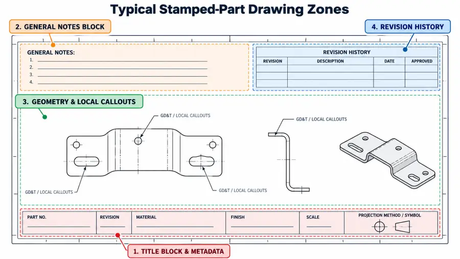
Standard layout zones on a 2D stamped-part drawing help organize title-block data, general notes, revision history, and local feature callouts.
Stamped Part Drawing Requirement Categories
Drawing Category
Typical Information
Why It Matters
Identification
Part number, title, revision, sheet number, scale, and projection method or symbol where applicable.
Establishes administrative control and helps manage documentation usage.
Material
Material grade, applicable material specification, certificate or traceability requirement where specified.
Helps ensure correct raw material selection and intended mechanical performance.
Thickness
Nominal thickness and applicable thickness requirement.
Influences tooling review, forming behavior, part stiffness, and manufacturing planning.
Material Condition
Temper, hardness, yield-strength class, or grain-direction requirement where specified.
Can affect springback behavior, formability, and mechanical performance.
Dimensions
Linear dimensions, angular controls, general block tolerances, and local feature callouts.
Controls physical size, fit, and spatial relationships of stamped features.
GD&T
Feature control frames, datum references, position, profile, and orientation controls.
Communicates functional relationships beyond conventional linear limits.
Edge / Burr
Burr direction, edge condition, or allowable burr requirement where functionally necessary.
Helps reduce interference, handling risk, or functional edge ambiguity.
Form / Flatness
Flatness controls, non-rigid part requirements, and defined verification conditions where applicable.
Defines controlled-surface and measurement requirements on the engineering drawing.
Finish
Finish or coating specification, dimensional state before/after finishing where relevant, and masking requirements.
Defines final surface condition and helps avoid dimensional ambiguity after finishing.
Inspection-Critical Notes
CTQ symbols, key characteristics, or special verification conditions where required.
Guides attention to product characteristics that require explicit verification.
Revision
Revision identifier, change reference where applicable, revision date, and change summary.
Helps ensure the supplier works to the current released product definition.
Part Number, Drawing Title, Units, and Revision
The drawing title block anchors the technical record. It should list the part number, descriptive part title, primary unit of measure, drawing scale, projection method where applicable, and current version level. If a drawing contains multiple pages, each page should display an explicit sheet identification number, such as “Sheet 1 of 2,” to help prevent missing documentation.
Material Grade and Governing Specification
Metal stamping raw materials vary in chemistry, tensile strength, yield strength, and formability. Vague terms such as “steel” or “stainless steel” leave raw-stock selection open to interpretation. The drawing should state the required alloy or grade alongside a recognized governing specification where required by the project.
Material Thickness and Condition
Sheet-metal thickness influences tooling review, forming behavior, and part strength. The drawing should state the nominal material thickness and its applicable requirement. In addition to nominal thickness, material condition—such as temper or hardness—should be specified when it affects manufacturing or final function.
How Should Material Requirements Be Written on the Drawing?
Material grade, thickness, and condition can influence tooling decisions, forming behavior, springback, and final part performance. Expressing material parameters clearly on the 2D print helps reduce raw-material ordering errors.
Material Grade vs. Material Standard
The material grade identifies the specific alloy or material designation, while the governing standard defines an external technical specification for manufacturing, testing, or chemical-composition limits.
Calling out an alloy grade alone may leave some procurement or technical requirements open to interpretation. Coupling the grade with an established standard can provide clearer boundaries for raw-material purchasing. Not every project requires a formal international standard reference, but applications with defined regulatory, functional, or customer requirements can benefit from explicitly stated material specifications.
Temper, Hardness, and Material Condition
Different material conditions can change strength, ductility, springback, and forming response. Where these characteristics affect manufacturing or final function, the required condition should be stated explicitly rather than left to supplier assumption.
Material Certificates and Traceability Requirements
When projects require material verification, the drawing note, purchase order, or associated quality document should indicate whether a Material Test Report (MTR), Material Test Certificate (MTC), lot traceability, heat-number records, or other compliance documentation is required. The correct location depends on the OEM’s document-control system and project requirements.
How Should Tolerances Be Communicated on a Stamped-Part Drawing?
Tolerances govern the allowable variation of physical features. Stamping drawings typically balance general title-block tolerances with local feature-specific tolerances to manage tooling cost and part functionality.
General Tolerances vs. Feature-Specific Tolerances
A general tolerance block establishes default tolerances for dimensions that do not carry an individual tolerance, according to the drawing’s stated convention or referenced standard.
Features that serve critical assembly functions—such as mating holes, datum-related cutouts, or controlled slot locations—may require explicit local tolerances. When a local feature-specific tolerance is applied directly to a dimension or feature control frame, it governs that specific geometry instead of the general title-block requirement.
Avoiding Conflicts Between General and Local Tolerances
Conflicting tolerance instructions increase supplier interpretation risk and can delay quotation. Common conflicts occur when:
A local dimension carries a tight tolerance, but an overall chain dimension relies on CAD geometry governed by a broader general note.
A drawing note specifies a tight linear tolerance for a formed feature while another instruction allows process variation that contradicts the limit.
A feature control frame specifies a geometric requirement that conflicts with an explicit plus/minus coordinate tolerance on the same feature.
Critical dimensions should be clearly identifiable, and conflicting tolerance paths should be eliminated before releasing the print.
How Should GD&T Be Used on Stamped Metal Parts?
Geometric Dimensioning & Tolerancing (GD&T) provides a standardized language to define feature relationships based on part function. Where that system governs the product definition, requirements should follow the applicable drawing standard, such as ASME Y14.5.
Use GD&T to Communicate Functional Relationships
Conventional plus/minus dimensions may not fully communicate functional relationships between features. GD&T can provide clearer control of location, orientation, form, and profile where those relationships matter to assembly or function. It can be useful for stamped parts to control:
Hole-pattern locations relative to mating interfaces.
Formed contours across complex stamped geometry.
Orientation of formed flanges or tabs relative to mounting references.
Flatness of primary interface faces.
Datum Selection for Stamped Components
Datums establish the reference frame used to define and verify geometric relationships. For stamped components, datum features should be:
Functionally Meaningful: Related to how the part is mounted, located, or used in its final assembly.
Repeatable & Stable: Selected from features that provide a practical and repeatable reference for assembly and inspection; flexible or unstable features should be avoided where they cannot establish a consistent datum.
Accessible: Practical for the intended verification method.
Thin or complex sheet-metal parts may use datum targets or other defined reference features when a complete surface does not provide a practical, repeatable reference.
Position, Profile, Flatness, and Orientation Controls
Common GD&T controls on stamped part drawings can include:
Position: May be used to control the location of holes, slots, or other features relative to a datum reference frame. Material-condition modifiers may be applied where appropriate to the design and functional requirement.
Profile of a Surface: Can be used to control complex formed surfaces or contours relative to the specified datum system and defined nominal geometry.
Flatness: Controls the variation of a surface within two parallel planes without reference to a datum.
Parallelism and Perpendicularity: Control orientation relative to specified datum features where needed.
How Should Burr and Edge Requirements Be Shown?
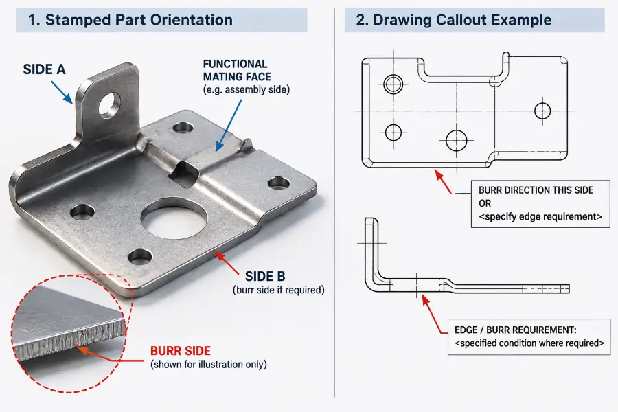
Shearing and piercing can leave a directional cut-edge condition. When that edge condition affects assembly, contact, safety, sealing, wiring, or appearance, the drawing should communicate the required burr direction or edge condition clearly.
Burr direction should be communicated on the drawing when the cut-edge condition affects a functional or mating surface.
Burr Direction
Burr direction can be important when:
A stamped component slides against an adjacent surface where a burr could cause scratching or binding.
An edge sits near insulated electrical wiring where a sharp edge could damage insulation.
A gasket or seal interfaces with the stamped surface.
An operator handles the component manually during assembly.
When burr orientation matters, the drawing should include an explicit note, leader line, orientation mark, or other clearly defined callout pointing to the affected face.
Edge Condition and Burr Limits
When edges must be controlled for safety or performance, the drawing should define allowable burr parameters or edge conditions where functionally required. Standardized drafting conventions such as ISO 13715 may be used for technical-product-documentation requirements covering edges of undefined shape.
Drawing notes should distinguish between non-critical sheared edges and functional edges that require a defined condition.
How Should Flatness and Flexible-Part Requirements Be Written?
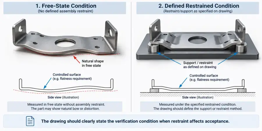
Flexible stamped components can produce different measured geometry depending on how they are supported or restrained. When this affects acceptance, the drawing should define the intended verification condition.
Flatness Callout
Vague notes such as “Must be flat” or “Keep flat” are difficult to verify objectively. A clear flatness specification identifies the controlled surface and defines the geometric requirement using the applicable drawing convention.
Free-State vs. Restrained Condition
Flexible stamped components may produce different measured results depending on support and restraint. ISO 10579 provides a formal framework for dimensioning and tolerancing non-rigid parts where restraint is required during verification.
When restraint affects acceptance, the drawing should state the verification condition instead of leaving support or restraint to supplier interpretation.
Free-State Condition: The specified requirement is evaluated without the defined assembly or inspection restraint, using the support and orientation condition established for verification.
Restrained Condition: The specified requirement is evaluated under the support, mounting, or restraint condition defined by the drawing or associated inspection requirement.
If a restrained condition is required, the relevant restraint or support parameters should be stated clearly rather than left to supplier assumption.
How Should Surface Finish and Plating Be Specified?
Surface treatments can provide corrosion protection, wear resistance, electrical functionality, or cosmetic finish. The engineering print should state finish requirements and dimensional timing clearly.
Define the Required Finish
Finish callouts should state the process type and applicable specification where required. Examples may include plating, passivation, anodizing, e-coating, powder coating, or other project-specific finishes. If appearance criteria, corrosion requirements, masking, or other functional conditions apply, these should be referenced clearly.
Before-Finish vs. After-Finish Dimensions
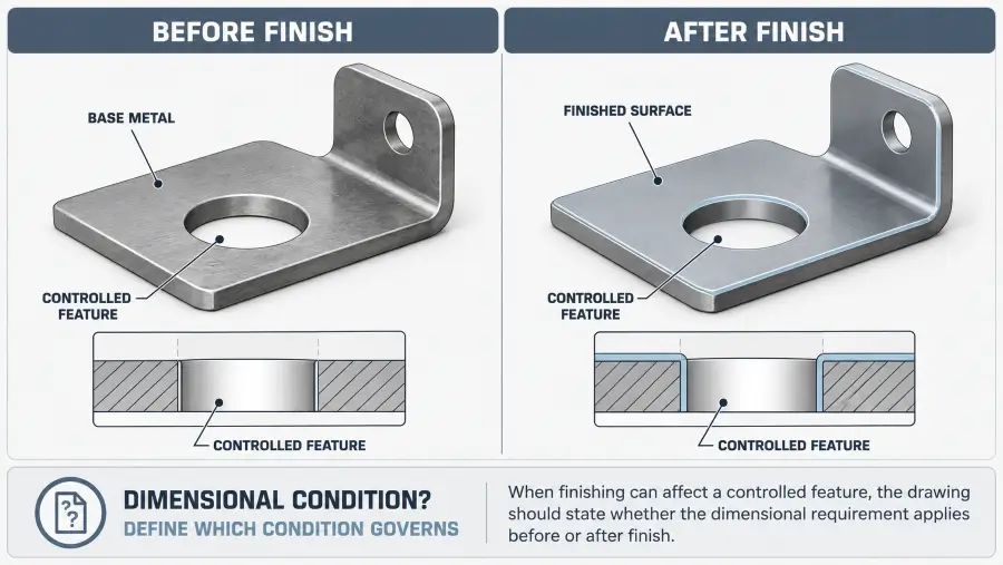
Coating or finishing can affect holes, slots, mating surfaces, and other tightly controlled features. The drawing should explicitly define whether controlled dimensions apply before or after finishing when the finish can materially affect the feature.
When finishing can affect a controlled feature, the drawing should state whether the dimensional requirement applies before or after finish.
Explicit drawing notes help reduce ambiguity on tightly controlled holes, slots, and mating interfaces.
Masking and No-Coating Areas
Where coatings could interfere with electrical grounding, thermal transfer, thread engagement, bonding, or precision interfaces, the drawing should identify required masking or no-coating zones.
What Belongs on the Drawing vs. the RFQ, PO, or Quality Plan?
An engineering drawing should contain permanent technical requirements that define the physical part. Dynamic commercial terms and project-level administrative requirements generally belong in procurement documents or quality agreements.
Drawing vs. RFQ / PO / Quality Document Matrix
Requirement
2D Drawing
RFQ / PO / Quality Document
Reason
Material Grade & Standard
Yes
Yes / Reference
Permanent product requirement needed for material purchasing and production.
Material Thickness
Yes
Yes / Reference
Product-definition requirement affecting tooling review and raw-stock purchase.
Critical Tolerances & GD&T
Yes
Reference if needed
Direct engineering definitions of feature size, form, location, and orientation.
Burr & Edge Requirements
Yes where applicable
Reference if needed
Physical edge condition tied to part function or acceptance.
Surface Finish Specification
Yes where applicable
Yes / Reference
Defines final surface condition and related manufacturing requirements.
Order Quantity / Batch Size
No
Yes
Dynamic commercial variable that should not normally force a drawing revision.
Delivery Schedule & Logistics
No
Yes
Commercial/program requirement subject to supply-chain scheduling.
Packaging Requirements
Project-dependent
Usually
Often controlled by PO, packaging specification, or logistics document.
First Article / FAI Requirement
Project-dependent
Usually
Program-level quality requirement typically controlled by the customer quality system.
Sampling Plan / AQL Level
Project-dependent
Usually
Lot-acceptance requirement generally defined in a quality plan or purchasing specification.
How Should 3D CAD and 2D Drawings Be Controlled?
Modern manufacturing relies on both 3D solid models and 2D engineering drawings. Mismatches between these files can create manufacturing risk during tooling and production planning.
Avoiding Conflicting Product Definitions
Discrepancies can occur when one product-definition source is revised without the related file being updated. Toolmakers or suppliers working from different released data may then interpret geometry differently.
Define the Governing Source
The OEM should explicitly identify the governing source of product definition if the 3D model and 2D drawing differ.
The correct precedence depends on the OEM’s product-definition system and should be stated rather than assumed. If both sources are released, the drawing or related document-control requirement should identify which one governs in the event of a discrepancy.
Why Drawing Revision Control Matters in Metal Stamping
Stamping dies can be long-life manufacturing assets, and drawing revisions may affect tooling that has already been designed, built, or modified. Working to an obsolete product definition can create tooling rework, material waste, or production delays.
Revision Identification
The released drawing should clearly identify its current revision or status. Revision history or change references should be maintained according to the OEM’s document-control system, with the applicable revision identifier, change description, date, or approval information captured where required.
When related 2D and 3D files are revised, their relationship should remain controlled and unambiguous.
Preventing Obsolete Drawing Use
The supplier should confirm it is working from the current released product definition before affected tooling changes or production decisions proceed.
Common Stamped-Part Drawing Mistakes
Incomplete or contradictory drawing callouts introduce manufacturing risks that can affect part quality, tooling decisions, or launch timing.
Common Stamped-Part Drawing Errors and Manufacturing Risks
Drawing Issue
Potential Manufacturing Risk
Better Drawing Practice
Material grade too generic
Supplier may quote or purchase an unintended material grade, potentially affecting performance or formability.
State the required material grade and applicable specification where needed.
Stock thickness omitted or vague
Tooling and process review becomes uncertain when nominal stock thickness is not clearly defined.
Provide nominal thickness and the applicable thickness requirement.
Material condition / temper unclear
May lead to unexpected forming response, springback, cracking risk, or altered mechanical performance.
Specify temper or condition when manufacturing or final function depends on it.
Critical vs. general tolerances unclear
Over-specifying non-critical features can raise tooling cost; under-specifying functional features can create assembly or acceptance risk.
Use general tolerances for suitable features and explicit local tolerances or GD&T where functional control is required.
Burr side or edge condition omitted
Burr orientation may conflict with a mating, sealing, wiring, or handling requirement.
Define burr direction or edge condition where functionally necessary.
Flatness condition unclear on flexible parts
Free-state and restrained measurements may produce different results, creating supplier-customer acceptance disagreement.
Define the controlled surface and state the verification condition where restraint affects acceptance.
Finish dimensional state omitted
Finishing can affect tightly controlled holes, slots, or mating features.
State whether controlled dimensions apply before or after finishing when relevant.
CAD vs. 2D drawing conflict
Tooling or inspection may be based on different product definitions.
Define the governing source of product definition.
Revision history out of sync
Supplier may work from an obsolete product definition.
Confirm that released product data and purchasing references point to the current approved revision/status.
Stamped Part Drawing Notes Template
The template below provides a reusable general-notes framework for custom metal stampings. It should be adapted to suit specific project requirements, company standards, and component functions.
FINISH TIMING: [Define dimensional condition before or after finish where relevant]
FORM & FLATNESS / RESTRAINT: [Specify free-state or restrained condition if required]
CRITICAL CHARACTERISTICS: [Identify CTQ symbols or key features where applicable]
DOCUMENT PRECEDENCE: [Define which released 2D drawing or 3D model governs if they conflict]
REVISION LEVEL: [Insert current released revision code / date]
Stamped Part Drawing Requirements Checklist
Before releasing a 2D stamped-part drawing for supplier quotation or production tooling review, use the following stamping supplier drawing checklist.
OEM Drawing Release Checklist
Requirement
Verified Before RFQ?
Part Identification: Part number, drawing title, scale, and projection method where applicable are identified.
□
Units of Measure: Linear units are clearly defined, with angular notation or units clarified where required.
□
Material Grade: Required material grade and governing specification are referenced where applicable.
□
Thickness: Nominal stock thickness and applicable requirement are defined.
□
Material Temper / Condition: Hardness, temper, or condition is noted where functionally relevant.
□
Tolerance Strategy: General tolerance convention is defined and local critical tolerances are applied where required.
□
GD&T & Datums: Datum references and functional geometric controls are defined where required.
□
Burr & Edge: Burr direction or edge condition is defined where functionally relevant.
□
Flatness / Restraint: Flexible-part verification condition is clarified where necessary.
□
Finish Specification: Finish, coating, or masking requirements are identified where applicable.
□
Finish Timing: Before-/after-finish dimensional condition is clarified where the finish can affect controlled features.
□
Document Precedence: Governing product definition is clarified where both 2D and 3D data are supplied.
□
Revision Control: Current released revision/status and applicable change history are confirmed.
□
What Information Should Be Included in the RFQ Package?
While the 2D engineering drawing defines the physical and functional part, a complete Request for Quotation (RFQ) package contains additional commercial and program context. Providing complete documentation up front helps suppliers evaluate tooling feasibility and quote more accurately.
A metal stamping RFQ package should typically include:
2D PDF Engineering Drawing: Complete drawing notes, dimensions, and specifications.
3D CAD Model: Neutral or native CAD data where available.
Estimated Production Volumes: Expected annual demand and typical batch quantities where known.
Program Timing: Expected project launch or delivery timing where relevant.
Tooling / Program Requirements: Customer-specific tooling ownership, lifecycle, transfer, maintenance, or program requirements where applicable.
Quality & Sample Requirements: First-article, material-certificate, dimensional-report, or other documentation expectations where required.
Packaging Requirements: Special handling, corrosion protection, trays, reels, or other packaging requirements where applicable.
Not all RFQ information belongs on the engineering drawing.
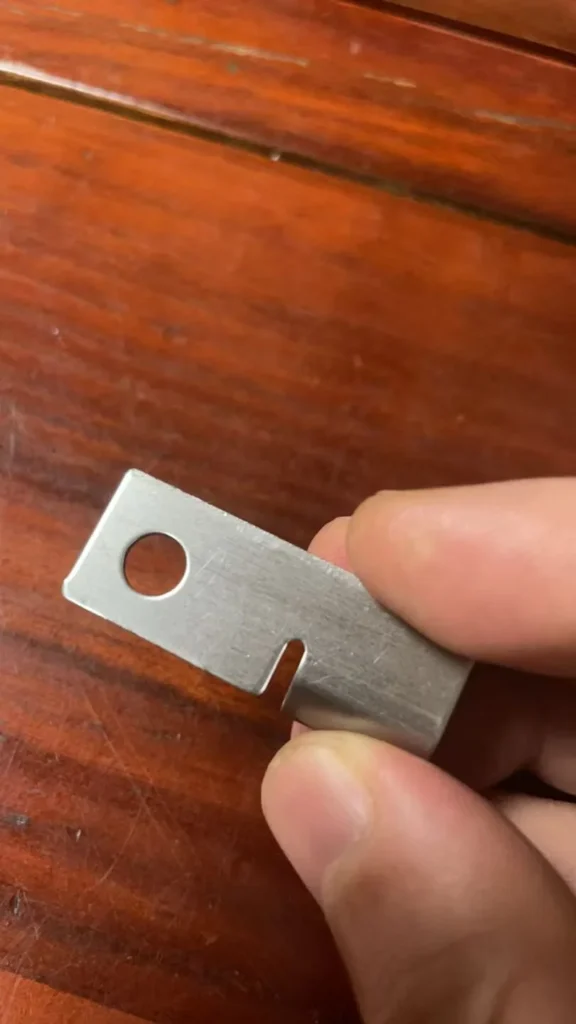
A real stamped metal part showing the physical features defined by the engineering drawing and manufacturing requirements.
From Our Stamping Experience: Clear Drawings Reduce Manufacturing Ambiguity
Metal Stamp Factory was established in 2014 in Xiamen, China, focusing on custom metal stamping and precision hardware manufacturing. The founder of Metal Stamp Factory, Shengtong Chen, started learning mold making and metal stamping at the age of 17 and has accumulated more than 25 years of hands-on manufacturing experience in tooling development, metal stamping, and OEM production.
Before tooling is finalized, we review the drawing package to understand the specified material, thickness, material condition where relevant, critical dimensions and tolerance relationships, GD&T requirements, burr or edge requirements, finish condition, inspection-critical requirements, and current revision.
Where requirements are missing or conflicting, clarification should occur before tooling decisions are finalized rather than relying on supplier assumptions. This can reduce the risk of later tooling changes, material waste, or launch delays.
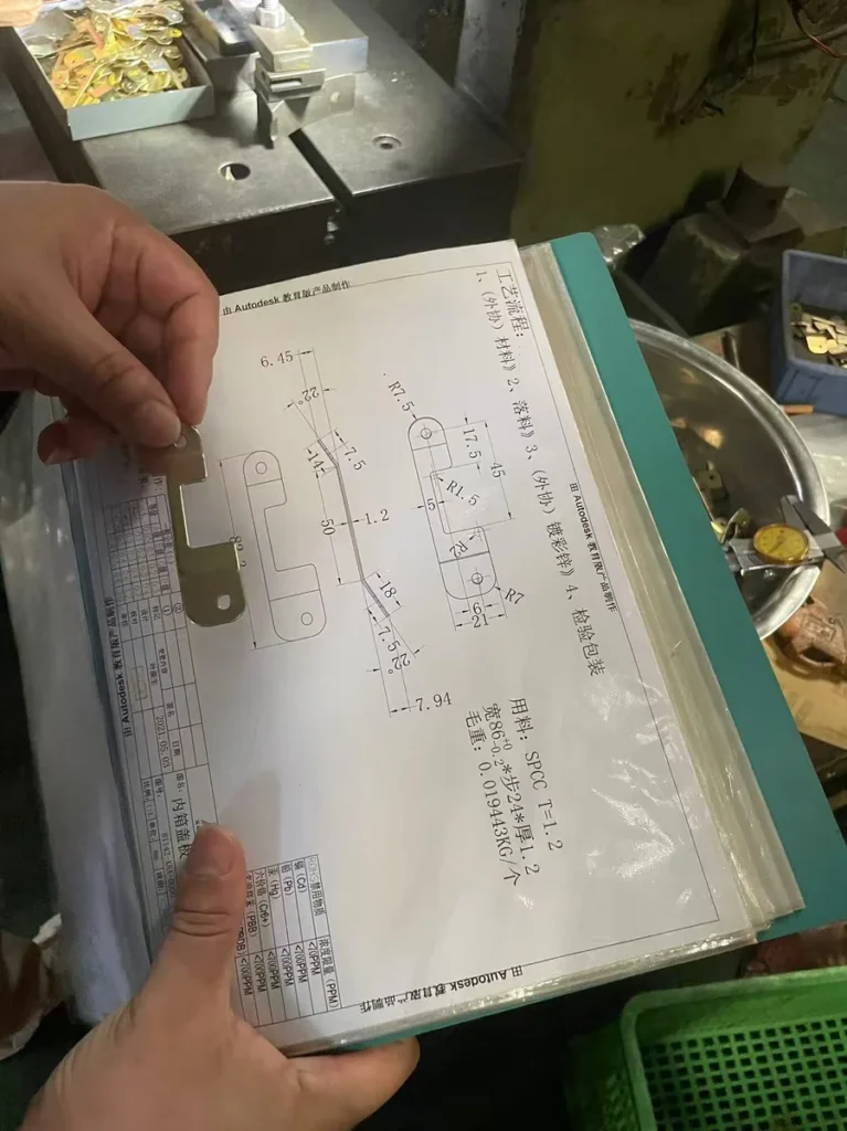
Reviewing drawing requirements alongside stamped components helps identify unclear specifications before tooling decisions are finalized.
Frequently Asked Questions About Stamped Part Drawing Notes
What information should be included on a stamped-part drawing?
A complete stamped-part drawing should include part metadata, material specifications, nominal thickness, material condition where needed, general and feature-specific tolerances, GD&T where required, burr or edge requirements, surface-finish information, dimensional state before or after finishing where relevant, flexible-part verification conditions where applicable, revision information, and document-precedence requirements when both 2D and 3D data are supplied.
Do stamped metal parts need GD&T?
Not every stamped part or feature requires GD&T. Conventional linear and angular tolerances may be sufficient for simple features. GD&T is useful where functional relationships—such as hole-pattern location, formed-surface profile, or feature orientation relative to mounting references—need clearer control.
How should material grade and thickness be specified on a stamping drawing?
The drawing should identify the required material grade, applicable specification where relevant, nominal thickness, and material condition or temper when it affects forming or final function.
How should burr direction be shown on a stamped-part drawing?
Burr direction can be shown using an explicit drawing note, leader line, orientation mark, or applicable edge-condition symbol where required by functional edge considerations.
Should stamped-part dimensions apply before or after plating?
The drawing should explicitly define whether controlled dimensions apply before or after coating when the finish can materially affect the feature.
How should flatness be specified for a flexible stamped part?
For flexible stamped parts, the drawing should identify the controlled surface and state whether verification is performed in the free state or under a defined restrained condition where applicable.
What should happen if the 3D CAD model and 2D drawing conflict?
If a discrepancy is discovered between the 3D CAD model and 2D drawing, the governing source of product definition should be clarified before affected tooling or production decisions proceed.
What information should a stamping supplier receive for an RFQ?
A stamping supplier should receive the 2D engineering drawing, 3D CAD data where available, material and thickness requirements, estimated quantities, finish requirements, tooling or program expectations, quality-document expectations, and other relevant project requirements.
Send Your Stamped-Part Drawing for Engineering Review
If you are developing a new custom metal stamping or preparing a 2D print for production release, our engineering team can review your drawing package for manufacturing feasibility and technical clarity.
When submitting an RFQ, please provide:
2D PDF engineering drawing.
3D CAD model where available.
Material grade, nominal thickness, and condition.
Finish or plating specifications where applicable.
Quantity and program expectations.
Special inspection or functional requirements where relevant.