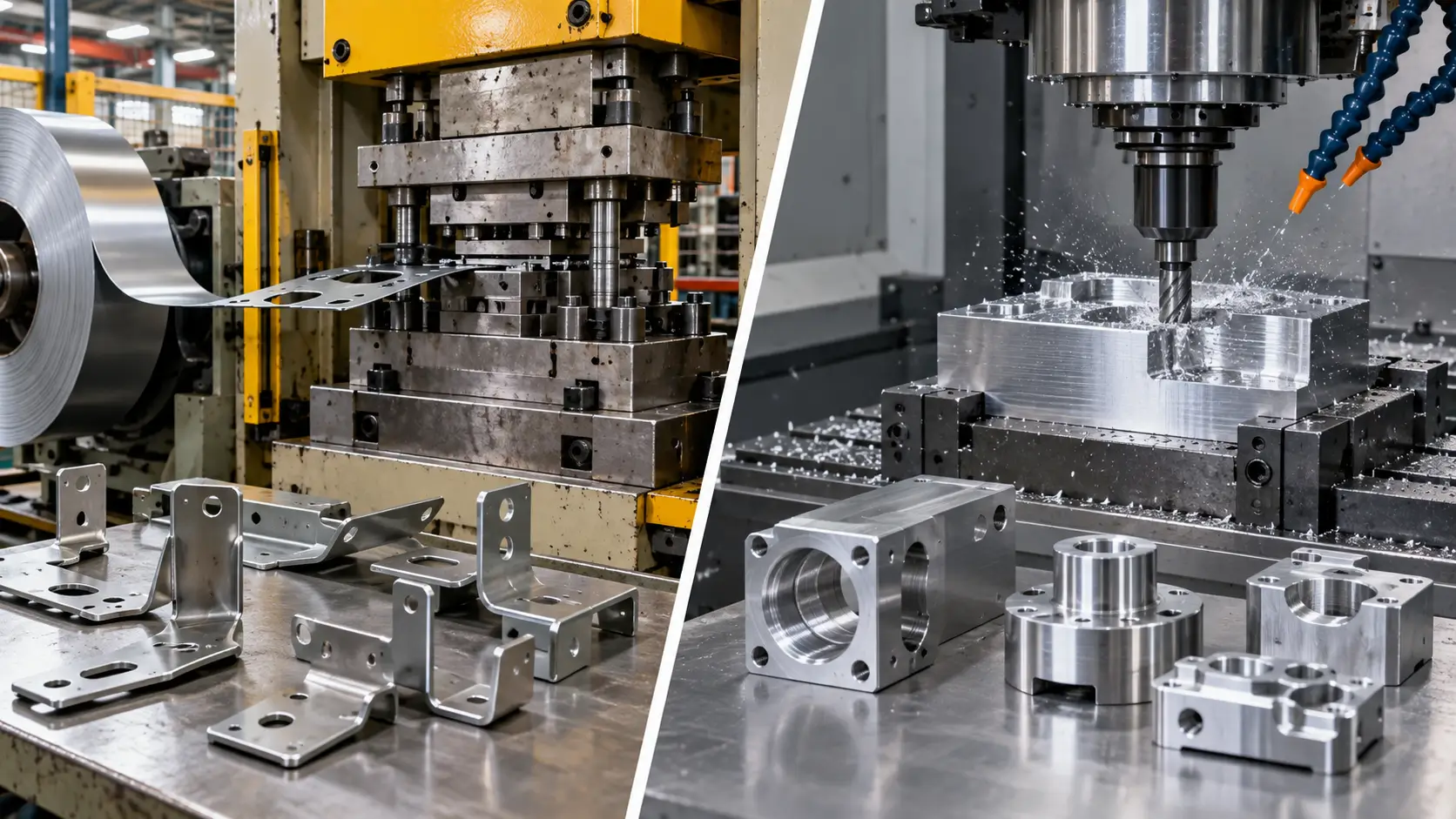
Achieving a precise metal stamping flatness tolerance is one of the most persistent engineering challenges in custom sheet metal manufacturing. Unlike simple linear dimensions such as length, width, or hole pitch, flatness is a geometric form control that reflects the interaction between raw material properties, stress release, part geometry, tooling architecture, and post-forming elastic recovery.
When a flat sheet metal component is sheared, pierced, formed, or released from press tooling, internal stresses can redistribute, which may cause the component to bow, dish, warp, or twist.
In OEM custom manufacturing, there is no universal metal stamping flatness tolerance that automatically applies to every component. An allowable flatness limit for a structural bracket can differ completely from that of an electrical contact, a deep-drawn housing, or a thin stamped component.
Acceptable out-of-plane variation depends on the functional requirement, material thickness, material properties and condition, component geometry, forming operations, tooling and process conditions, and the measurement condition used during inspection.
For OEM design engineers, manufacturing teams, quality engineers, and technical buyers, controlling stamped part flatness therefore requires more than simply adding a tight tolerance to a drawing. It requires understanding what causes sheet metal distortion, how GD&T flatness works, when correction operations may be justified, and how inspection conditions should be communicated.
Metal Stamping Flatness Tolerance — Quick Answer
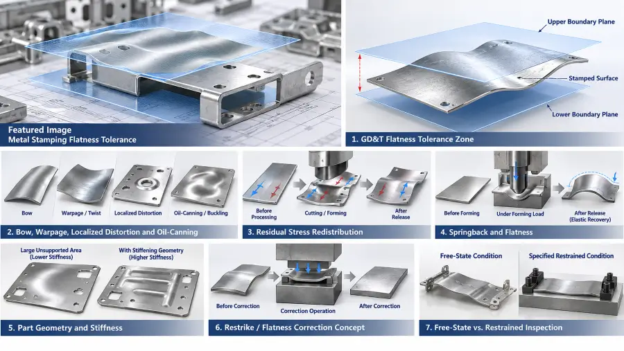
A metal stamping flatness tolerance defines a three-dimensional geometric zone bounded by two parallel planes within which the surface points of a specified stamped component surface must lie.
There is no single universal industry value for stamped-part flatness because out-of-plane distortion can be influenced by material thickness, mechanical properties, material condition, part geometry, internal residual stresses, forming operations, and the way the part is supported or restrained during inspection.
Key engineering considerations include:
- Function drives the requirement: Flatness should be based on actual assembly or performance needs rather than arbitrary maximum precision.
- Geometry and material influence achievability: Large unsupported areas, asymmetric features, material condition, and part stiffness can influence distortion.
- Measurement condition matters: Flexible stamped parts may change shape depending on gravity, support, or restraint.
- Process options are application-specific: Tooling sequence, material support, forming strategy, restrike, or flattening may help in some applications, but none should be treated as a universal solution.
What Is Flatness in Metal Stamping?
In sheet metal manufacturing, flatness describes how closely a specified surface approaches a planar condition.
During stamping, sheet metal can undergo localized shearing, stretching, compression, and bending. These operations can change the stress equilibrium of the material and allow the finished component to deviate from a flat plane after it is released from the tooling.
How GD&T Flatness Is Defined
Under engineering drawing frameworks such as ASME Y14.5 and ISO 1101, flatness is a form control.
A surface flatness tolerance controls the form of the specified surface without referencing a datum.
Important characteristics include:
- Parallel-plane tolerance zone: The tolerance establishes a zone bounded by two parallel planes.
- Datum independence: Flatness controls the form of the surface itself rather than its orientation relative to another feature.
- Surface control: The requirement applies to the specified physical surface.
- Drawing communication: The flatness symbol and tolerance value communicate the permitted surface-form variation.
Flatness vs. Bow, Warpage, and Distortion
Several terms are used in stamping plants and engineering discussions to describe parts that do not remain flat.
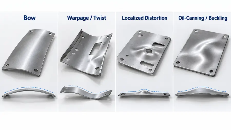
- Bowing: A relatively continuous curvature across the length or width of a part.
- Warpage or twist: Multi-directional distortion that may cause opposite corners or different areas to lift.
- Localized distortion: Out-of-plane deformation concentrated around openings, formed features, narrow webs, or other local geometry.
- Oil-canning or buckling: Instability in a relatively thin panel where an area can move between different curved states.
These terms help describe observed physical conditions, but they should not be treated as interchangeable formal GD&T controls.
Stamped Part Distortion Modes: Characteristics and Engineering Checks
| Distortion Mode | Typical Appearance | Possible Contributors | Engineering Checks |
|---|---|---|---|
| Bow | Smooth or gradual curvature across the part length or width. | Incoming coil condition, residual stress redistribution, cutting conditions, material direction, or forming history. | Review incoming material condition, strip direction, straightening where applicable, tooling condition, and process sequence. |
| Warpage / Twist | Multi-directional deformation or opposite corners lifting. | Asymmetric geometry, uneven deformation, forming sequence, material-direction effects, or separation from the carrier. | Compare distortion with feature layout and material direction; review forming, support, and separation sequence. |
| Localized Distortion | Local waviness or deformation near holes, slots, formed features, or narrow webs. | Localized strain, uneven stress release, feature concentration, insufficient support, or cutting/forming sequence. | Review feature layout, local stiffness, tooling support, and operation sequence. |
| Oil-Canning / Buckling | A broad thin area that can move between curved states under relatively light pressure. | Panel geometry, low stiffness, compressive stress state, formed boundaries, or stress redistribution. | Review panel geometry, stiffness, formed edges, material condition, and whether design changes could improve structural rigidity. |
Is There a Standard Metal Stamping Flatness Tolerance?
There is no universal numerical flatness tolerance that automatically applies to all stamped metal components.
ASME and ISO standards provide standardized geometrical tolerancing language, but the numerical flatness requirement still needs to be selected according to the component’s function and applicable engineering requirements.
For a broader discussion of dimensional requirements in stamped parts, see our guide to metal stamping tolerances.
ASME Y14.5 and ISO 1101
ASME Y14.5 and ISO 1101 provide frameworks for communicating geometrical requirements such as flatness on engineering drawings.
They should not be interpreted as universal manufacturing charts that assign one numerical stamped-part flatness tolerance based solely on material or thickness.
Raw Material Flatness vs. Finished Stamped-Part Flatness
Raw sheet or coil requirements and finished stamped-part flatness are different engineering issues.
Incoming material may comply with the applicable material specification while the finished component still develops bow, twist, or other distortion during manufacturing.
This is because stamping changes the part:
- Cutting changes material continuity.
- Piercing introduces additional edges and local deformation.
- Forming changes the stress state.
- Springback occurs after forming loads are removed.
- Separation from a strip or carrier can change how stresses are distributed.
Therefore, acceptable incoming sheet condition does not automatically guarantee acceptable stamped part flatness.
What Causes Flatness Problems in Stamped Parts?
Flatness problems are rarely explained by one universal cause. The observed condition may result from interactions between material condition, geometry, tooling, forming history, and process sequence.
Observation: Overall Bow Across the Part
Possible contributors may include incoming material condition, coil set, residual stress redistribution, cutting conditions, or forming history.
Engineering checks can include reviewing incoming material, strip direction, straightening conditions where applicable, tooling condition, and the point in the process at which the bow first becomes visible.
Observation: Local Distortion Near Openings or Formed Features
Possible contributors may include concentrated openings, narrow webs, asymmetric geometry, local strain, cutting sequence, or insufficient material support.
Engineering teams should review the relationship between the distortion and nearby holes, slots, bends, embosses, or other formed features.
Observation: Twist Across the Part
Possible contributors may include asymmetric geometry, unbalanced deformation, material-direction effects, forming sequence, or strain introduced during final separation.
The distortion pattern should be compared with part geometry and process sequence rather than automatically assigned to one tooling defect.
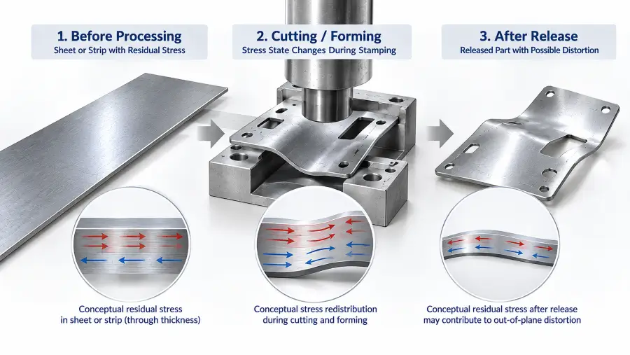
How Residual Stress Affects Stamped-Part Flatness
Residual stress is one possible contributor to out-of-plane distortion.
Sheet metal arriving from rolling, annealing, leveling, or coiling operations can contain internal stress distributions. Cutting and forming can alter this equilibrium.
Relevant factors include:
- Coil history and coil set: Coil-fed material may retain curvature or non-uniform stress.
- Shearing and piercing: Cutting changes material continuity and can redistribute stress around newly created edges.
- Localized deformation: Cutting and forming can create areas with different deformation histories and mechanical responses.
When the stamped component is released from tooling or separated from a carrier strip, a new mechanical equilibrium can develop. Bowing, twisting, or localized distortion may become more visible at this stage.
How Springback Affects Flatness
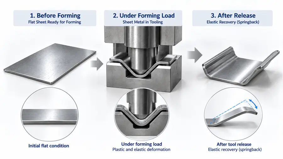
Springback is the elastic recovery of sheet metal after forming load is removed.
During bending or forming, part of the deformation is permanent while another portion is elastically recoverable. When the tooling opens, this elastic recovery can change angles and influence nearby surfaces.
The amount and pattern of springback can depend on:
- material grade;
- material condition;
- thickness;
- geometry;
- forming severity;
- tooling geometry;
- previous deformation history.
Springback does not always produce the same type of flatness problem. Depending on the component, it may contribute to crowning, bowing, angle change, or other out-of-plane variation.
How Part Geometry Influences Flatness
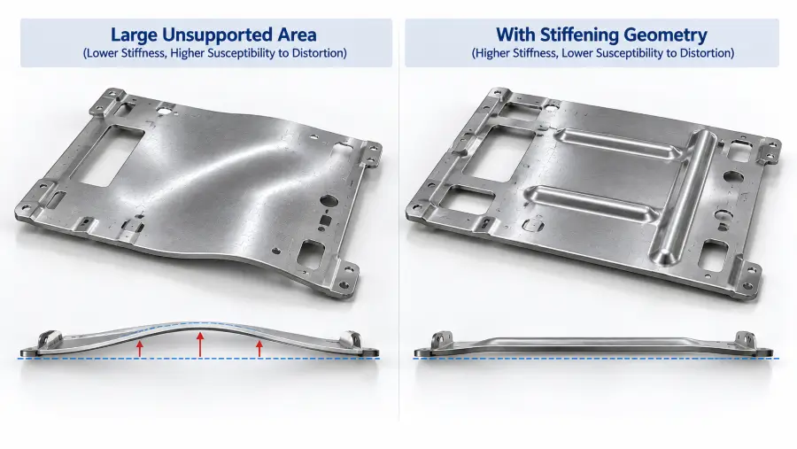
Part geometry affects both structural stiffness and how deformation is introduced during stamping.
Important factors include:
- large unsupported flat areas;
- relatively low part stiffness;
- asymmetric holes or cutouts;
- narrow webs;
- formed flanges;
- embossed or stiffening features;
- uneven distribution of formed features.
Stiffening features such as suitable ribs, beads, or flanges can increase structural rigidity in appropriate designs, but they should not be treated as a universal cure for flatness problems.
For broader geometry considerations such as hole margins, edge distances, bend radii, and feature spacing, see our metal stamping design guidelines.
How Tooling and Stamping Sequence Affect Flatness
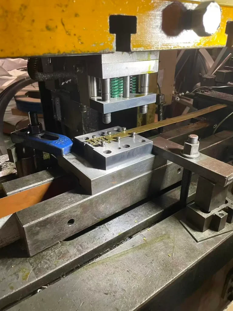
Tooling configuration and stamping sequence can influence how material is supported, cut, formed, and released.
Relevant considerations include:
- material support during cutting and forming;
- stripper or pressure components where applicable;
- punch and die condition;
- cutting clearance;
- sequence of piercing and forming operations;
- carrier-strip behavior in progressive stamping;
- final separation from the strip or carrier;
- correction operations where technically justified.
No single die architecture should be assumed to produce better flatness in every application. The tooling concept must be evaluated against part geometry, material, forming requirements, production volume, and functional tolerance.
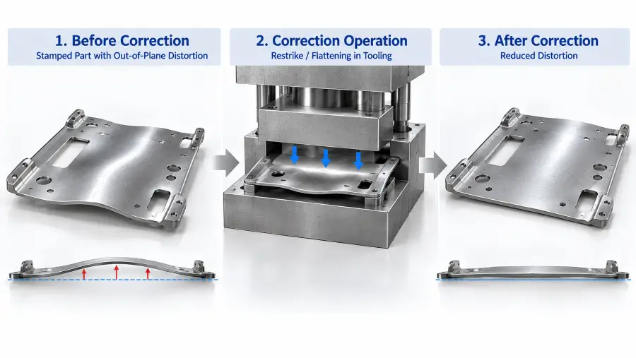
Restrike, Flattening, and Other Flatness-Correction Methods
When primary stamping operations do not consistently achieve the required shape, additional correction operations may be considered.
Possible methods include:
- Restrike: A subsequent controlled forming operation used to modify final geometry.
- Flattening: A dedicated operation intended to manage certain forms of bowing or distortion.
- Leveling of suitable blanks: In some manufacturing routes, leveling may be considered before later forming operations.
The effectiveness of these methods depends on material, material condition, thickness, geometry, previous forming history, tooling design, and the actual source of distortion.
They should therefore be treated as application-specific process options rather than guaranteed solutions.
How Should Flatness Be Specified on an Engineering Drawing?
Clear drawing communication helps align design, manufacturing, and inspection.
Surface Flatness and the GD&T Callout
A flatness requirement should clearly identify the controlled surface and state the required tolerance using the applicable drawing standard.
The drawing should not rely on an assumed shop standard where flatness is functionally important.
Flatness vs. Parallelism and Surface Profile
Flatness, parallelism, and surface profile serve different purposes.
- Flatness controls the form of a specified surface without referencing a datum.
- Parallelism controls orientation relative to a datum.
- Surface profile can control a broader three-dimensional surface relationship.
The correct control depends on what the component must do in the final assembly.
Avoiding Unnecessarily Tight Flatness Requirements
Tighter is not automatically better.
An unnecessarily tight flatness requirement can increase:
- tooling complexity;
- correction operations;
- process-control requirements;
- inspection complexity;
- supplier-buyer acceptance risk.
Flatness should therefore be based on functional requirements rather than a general preference for the smallest possible tolerance.
Free-State vs. Restrained Inspection for Flexible Stamped Parts
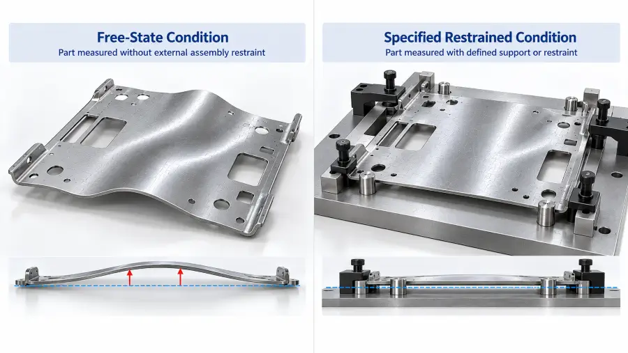
Flexible stamped components can change shape depending on gravity, support, orientation, and restraint.
This makes the inspection condition especially important.
- Free-state inspection: Evaluates the component without an externally imposed assembly restraint.
- Restrained inspection: Evaluates the component under a defined restraint condition where this is required by the drawing or functional condition.
- Support condition: Even free-state measurement requires an appropriate and understood setup.
- Drawing communication: Where restraint is necessary, the drawing and inspection agreement should define the relevant condition.
ISO 10579 provides relevant guidance for dimensioning and tolerancing non-rigid parts where restraint is required during verification.
Free-state and restrained measurements should not be casually mixed when deciding whether a flexible stamped component meets its requirement.
How Is Flatness Measured on Stamped Parts?
The appropriate measurement method depends on part rigidity, geometry, tolerance requirement, inspection purpose, and production context.
For broader guidance on inspection stages, tool selection, documentation, sampling, and final acceptance, see our metal stamping quality inspection guide.
Common approaches include surface-plate methods, indicator-based checks, CMM measurement, optical measurement, and dedicated production checking methods.
Surface Plate and Indicator-Based Checks
A surface plate and indicator can be useful for suitable components when the setup and interpretation are clearly defined.
Part support matters, especially for flexible components.
Feeler Gauge or Gap Screening
Gap checks can provide useful production information for suitable parts, but a measured gap against a reference surface should not automatically be treated as equivalent to formal GD&T flatness evaluation.
CMM Measurement
Coordinate measuring equipment can collect multiple surface points and evaluate measured geometry.
Results depend on measurement strategy, support, point distribution, probe characteristics, and evaluation method.
Optical and 3D Measurement
Non-contact systems can provide broader surface data where suitable equipment and measurement procedures are available.
Their suitability depends on the component, surface condition, equipment capability, setup, and required verification.
Dedicated Production Checking Methods
Part-specific fixtures or other production checks can provide rapid feedback during repetitive manufacturing.
A functional or restrained production check should not automatically be described as free-state GD&T flatness measurement.
Flatness Measurement Methods for Stamped Parts
| Method | Best Used For | What It Evaluates | Key Considerations |
|---|---|---|---|
| Surface Plate + Indicator | Suitable rigid or semi-rigid components and controlled dimensional checks. | Surface variation according to the defined indicator setup. | Support, orientation, indicator path, part rigidity, and interpretation can affect the result. |
| Feeler Gauge / Gap Screening | Rapid production or receiving checks where gap information is functionally useful. | Gap between the part and a reference surface at selected locations. | This is a gap check and should not automatically be treated as equivalent to formal GD&T flatness evaluation. |
| CMM | Coordinate-based dimensional inspection where appropriate for the component. | Spatial surface-point data according to the selected measurement and evaluation strategy. | Point distribution, support, probe characteristics, software evaluation, and part flexibility should be considered. |
| Optical / 3D Measurement | Non-contact surface mapping where broader surface information is required. | Surface data captured without conventional contact probing. | Equipment capability, calibration, reflectivity, surface condition, setup, and evaluation method affect suitability. |
| Dedicated Production Checking Method | Repetitive production checks developed for a specific component. | A defined dimensional or functional condition. | The method may represent a functional or restrained condition rather than formal free-state flatness. |
Why Measurement Setup Matters
A flatness result can depend strongly on the setup used to obtain it.
Variables include:
- gravity;
- orientation;
- support locations;
- part flexibility;
- fixture restraint;
- clamping conditions where specified;
- repeatability of the setup.
For flexible stamped parts, a flatness number without a clearly understood measurement condition can create disagreement between supplier and customer even when both parties believe they are following the drawing.
How to Control Flatness During Production
Flatness control should be approached as part of the overall manufacturing process rather than as a final inspection problem only.
Useful control activities can include:
- verifying material grade, thickness, and material condition;
- reviewing incoming strip or sheet condition where relevant;
- monitoring feed and straightening conditions in coil-fed production;
- maintaining punches, dies, and other tooling components;
- reviewing material support and stripping conditions;
- monitoring process changes;
- checking critical geometry using an appropriate inspection method;
- investigating trends before assuming one root cause.
Key Process Variables Influencing Stamped-Part Flatness
| Manufacturing Stage | Variable to Review | How It May Influence Flatness | What to Check |
|---|---|---|---|
| Incoming Material | Material grade, thickness, condition, and incoming sheet or strip shape. | Material condition and existing shape or stress state may influence behavior after cutting and forming. | Confirm specified material, thickness, relevant condition, and incoming material consistency. |
| Feed / Straightening | Coil feed and straightening conditions where applicable. | Incoming coil shape and straightening can influence strip condition before stamping. | Review feed alignment and straightening setup where relevant. |
| Blanking / Piercing | Cutting conditions, clearance, tool condition, and operation sequence. | Cutting may redistribute stress and influence local edge deformation. | Inspect tool wear, cutting condition, feature sequence, and the relationship between distortion and pierced geometry. |
| Forming | Forming sequence, material support, forming severity, and springback. | Plastic deformation and elastic recovery may change adjacent surfaces. | Review forming sequence, support, geometry, material behavior, and distortion after tool release. |
| Correction Operations | Restrike or flattening where technically justified. | Additional controlled deformation may help manage final geometry in some applications. | Verify that the correction addresses the observed distortion without assuming universal effectiveness. |
| Part Separation | Separation from the carrier or strip where applicable. | Release from the carrier may change the mechanical equilibrium of the part. | Compare part condition before and after final separation. |
OEM Flatness Specification Checklist
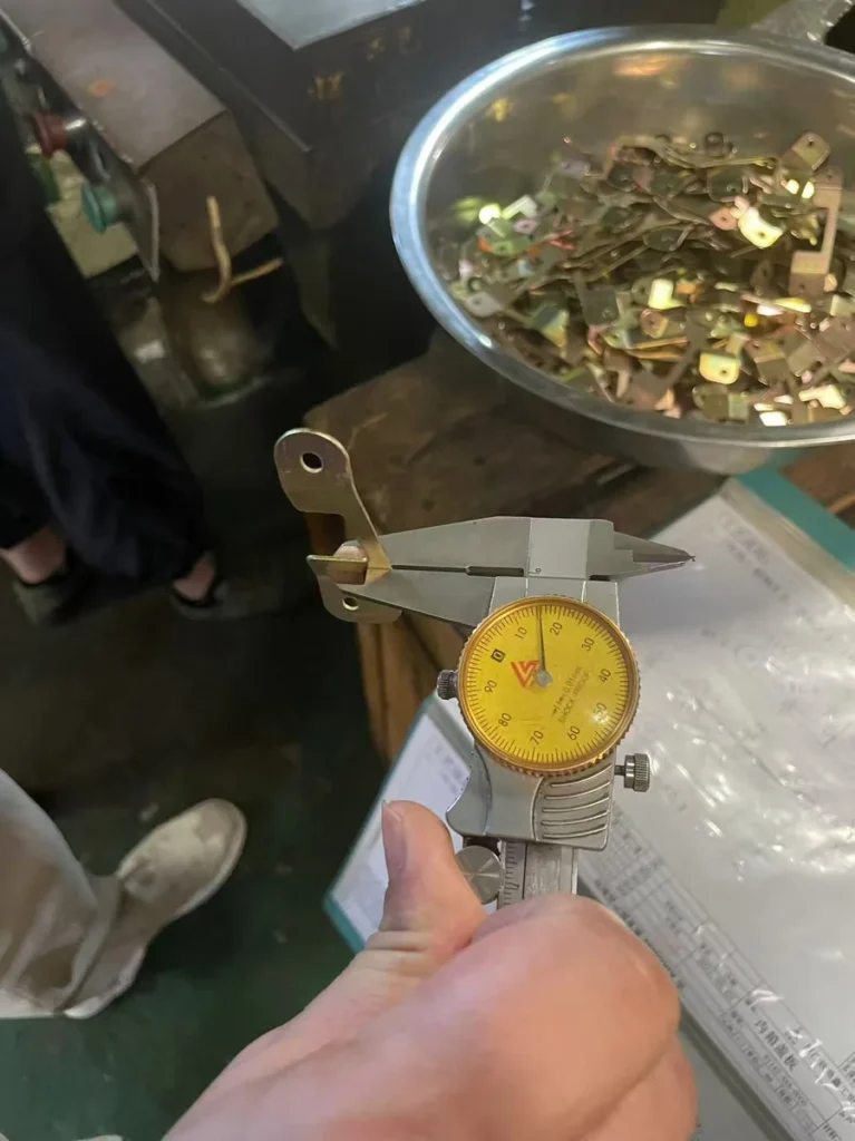
Before releasing an RFQ or production drawing for a stamped component with a critical flatness requirement, OEM engineers should define enough information for the supplier to understand both the tolerance and its functional context.
OEM Engineering Specification Checklist for Stamped Flatness
| Specification Item | Why It Matters | What the OEM Should Provide |
|---|---|---|
| Functional Requirement | Explains why flatness matters to the assembly or product. | Identify whether the requirement relates to sealing, thermal contact, sliding, positioning, assembly, appearance, or another relevant function. |
| Material Grade | Material properties influence forming behavior and springback. | Specify the exact required material grade. |
| Material Condition / Temper | Material condition can influence formability and response to forming. | Specify the required condition or temper where relevant. |
| Thickness | Thickness influences part stiffness and forming behavior. | Provide the required nominal sheet thickness and applicable drawing or material requirements. |
| Controlled Surface & Flatness Requirement | Prevents ambiguity about which surface is being evaluated. | Clearly identify the controlled surface and required flatness tolerance. |
| Free-State or Restrained Condition | Flexible parts may produce different measured results depending on support or restraint. | State the intended verification condition where relevant. |
| Inspection / Verification Method | Helps align supplier and customer acceptance. | Define the required or mutually agreed measurement approach where the method materially affects the result. |
| Production Quantity / Tooling Context | Manufacturing strategy and process-control approach can depend on production requirements. | Provide expected production quantity and relevant tooling or program information. |
From Our Stamping Experience: Flatness Is a Material–Geometry–Process Problem
Metal Stamp Factory was established in 2014 in Xiamen, China, focusing on custom metal stamping and precision hardware manufacturing.
The founder of Metal Stamp Factory, Shengtong Chen, started learning mold making and metal stamping at the age of 17 and has accumulated more than 25 years of hands-on manufacturing experience in tooling development, metal stamping, and OEM production.
From our stamping experience, flatness should not be evaluated as an isolated tolerance number.
Out-of-plane distortion can result from the combined effects of:
- material grade and condition;
- thickness;
- component geometry;
- forming severity;
- die clearance;
- forming force;
- springback;
- tooling condition;
- stamping sequence.
For formed stainless steel components, material condition can be especially important. SUS304 can work-harden during forming. For deeper drawing or more severe forming, annealed material may be required depending on the geometry and process.
For an OEM drawing review, we therefore consider the drawing, material specification, thickness, geometry, forming requirements, functional requirement, and inspection condition together before determining an appropriate manufacturing approach.
Frequently Asked Questions About Metal Stamping Flatness Tolerance
Is there a standard flatness tolerance for stamped metal parts?
No universal numerical flatness tolerance applies to every stamped metal part.
The appropriate requirement depends on component function, material, thickness, geometry, manufacturing process, and inspection condition.
Does GD&T flatness require a datum?
A surface flatness tolerance controls the form of the specified surface without referencing a datum.
This differs from orientation controls such as parallelism, which establish a relationship to a datum.
What causes stamped sheet metal to warp?
Possible contributors include incoming material condition, residual stress redistribution, cutting and forming operations, springback, asymmetric geometry, tooling conditions, and process sequence.
The observed distortion should be investigated rather than automatically attributed to one cause.
Can restrike improve flatness?
Restrike can help manage final geometry in some applications, but its effectiveness depends on material, thickness, geometry, forming history, tooling design, and the source of distortion.
It should not be treated as a guaranteed solution.
How is flatness measured on a stamped part?
Depending on the component and requirement, methods may include surface-plate and indicator checks, CMM measurement, optical or 3D measurement, and dedicated production checking methods.
The measurement condition and part support should be understood when interpreting the result.
Should thin stamped parts be measured free state or restrained?
That depends on the drawing requirement and functional condition of the component.
Drawings should clearly define whether flatness is evaluated in the free state or under a specified restrained condition. ISO 10579 provides relevant guidance for dimensioning and tolerancing non-rigid parts where restraint is required during verification.
Does tighter flatness always mean a better stamped part?
No.
A tighter flatness tolerance is useful when the component function requires it. Unnecessarily tight requirements can increase manufacturing and inspection complexity without improving final assembly performance.
Can raw sheet flatness guarantee finished stamped-part flatness?
No.
Incoming material condition is only one factor. Cutting, piercing, forming, springback, stress redistribution, tooling conditions, and release from the die can change the final shape of the stamped component.
Get an Engineering Review for Your Stamped Part
If you are developing a custom stamped metal component with critical flatness or geometric form requirements, an early manufacturing review can help identify potential conflicts between functional requirements, material behavior, part geometry, tooling, and inspection conditions before production tooling is finalized.
For an engineering review, please provide:
- complete 2D engineering drawings, including applicable GD&T requirements;
- 3D CAD files where available;
- material grade;
- material condition or temper where relevant;
- sheet thickness;
- required flatness and controlled surface;
- functional or assembly condition;
- free-state or restrained requirement where applicable;
- expected production quantity and tooling requirements.
Metal Stamp Factory can review these requirements as part of the custom metal stamping manufacturing evaluation before production.