Founder of Metal Stamp Factory with more than 25 years of hands-on experience in tooling development, metal stamping, and OEM production.
Introduction
Surface quality is critical in precision sheet metal processing, especially for functional components, aesthetic housings, and assembly-critical hardware. During press runs, surface defects can appear in various forms, ranging from subtle drag lines to severe material gouging. Diagnosing these defects correctly is essential for maintaining efficient production and protecting tooling assets.
Two terms frequently discussed together—and often confused—are galling and surface scratches. Galling in metal stamping refers specifically to an adhesive material-transfer mechanism that occurs under sliding contact, high friction, and local lubricant breakdown. A surface scratch, by contrast, is a broad visual symptom describing a linear groove or score on the sheet metal surface, which may be caused by galling, damaged tooling, trapped debris, surface contamination, or handling contact.
Not every surface scratch is galling, and addressing every mark as a tool-pickup issue can lead to unnecessary tooling modifications when simple contamination control or lubricant adjustment is required. Conversely, misinterpreting true metal pickup as random environmental scratching can allow adhesive transfer to build up and may increase the risk of further surface damage or tooling problems.
To resolve surface defects effectively, pressroom teams and quality engineers rely on a fundamental diagnostic principle:
Scratch appearance, location, direction, and repeat pattern are diagnostic clues, not proof of a single root cause.
Evaluating these clues systematically helps engineers identify whether a surface issue stems from adhesive wear, physical tooling damage, material contamination, or process variables. Galling and surface scratches are part of the broader group of common metal stamping defects that require root-cause review.
What Is Galling in Metal Stamping?
How Galling Develops During Sliding Contact
Galling is an adhesive wear process that occurs when two metallic surfaces slide against each other under high contact pressure. The Fabricator provides additional technical background on the root causes of die galling. In metal stamping—particularly in drawing, forming, flanging, and deep bending operations—the sheet metal slides continuously across tool radii, punch faces, and die cavity walls.
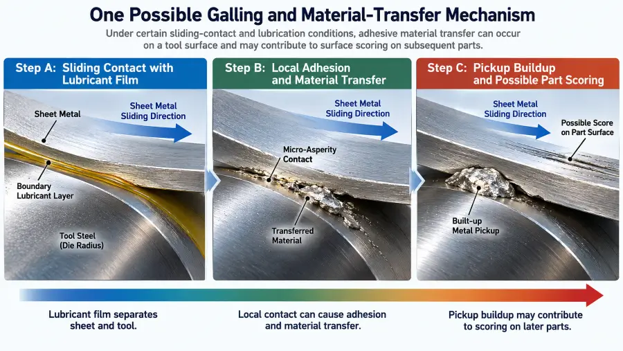
When operating conditions are favorable, a continuous lubricant film separates the sheet material from the tool surface. However, under high contact severity, local heat generation, or uneven oil application, this protective layer can break down. One possible progression can be described through the following mechanical stages:
- Sliding Contact: The sheet metal moves against the punch or die radius under intense local holding or forming pressure.
- Lubricant Film Breakdown: High local contact stress or thermal loads disrupt the boundary lubricant layer, leading to direct metal-to-metal contact between surface asperities (microscopic peaks).
- Adhesion and Micro-Welding: High friction and localized pressure cause minute points of the sheet material to cold-weld or adhere to the tool surface.
- Material Transfer: As sliding continues, small fragments of workpiece material may transfer and remain bonded to the contacting tool surface.
- Pickup Buildup: Subsequent stamping strokes pass over this initial transfer layer. Additional workpiece material may accumulate at the same area, forming a raised transfer layer or “pickup” on the tool.
- Scoring on Subsequent Parts: A raised pickup can then interfere with subsequent sliding contact and may create scoring or drag marks on later parts.
This progression illustrates one way localized friction and material transfer may develop into more visible surface scoring.
What Does Metal Pickup Look Like?
On the tooling side, metal pickup appears as localized lumps, patches, or smeared layers of transferred workpiece material firmly bonded to contacting radii, draw walls, or wipe dies. These areas often look rough, discolored, or slightly raised relative to the surrounding polished tool steel.
On the stamped component, galling-related surface damage may appear as localized drag marks, scoring, gouges, or burnished tracks along a sliding-contact path. If material pickup continues to build on the tool, the corresponding surface mark may become more pronounced on later parts.
While these visual characteristics strongly indicate adhesive material transfer, visual appearance alone does not provide absolute proof of galling. Inspection of both the part and the contacting tool surface is useful for confirming whether bonded metal pickup is actually present.
Galling vs. Surface Scratching
To prevent misdiagnosis, it is essential to distinguish between true adhesive galling and other forms of surface damage. The following table highlights key differences among common contact-related defects observed in metal stamping.
| Condition | What It Describes | Typical Mechanism | What May Be Seen |
|---|---|---|---|
| Galling | Severe adhesive wear involving localized material transfer between sheet and tooling. | Boundary lubricant breakdown under sliding contact, leading to micro-welding, metal pickup, and subsequent scoring. | Raised metallic pickup on the die surface; deep, continuous, stroke-parallel gouges or burnished drag tracks on the part. |
| Abrasive Scratching | Mechanical cutting or displacement of sheet material by a hard, rough surface. | Direct sliding contact across rough tool steel, unpolished grind marks, or sharp tool edges. | Fine, uniform parallel scratch lines matching the grinding or machining texture of the contacting tool surface. |
| Debris-Related Marks | Surface indentations or irregular scratches caused by foreign material trapped in the die. | Loose scale, environmental grit, or metal slivers caught between the blank and the tool during forming. | Intermittent, isolated, or wavy scratch marks; irregular pits or small surface indentations across the part face. |
| Tooling / Contact Marks | Non-adhesive surface impressions resulting from mechanical pressure or feeding interaction. | High local contact stress, stock guide contact, feed roller pressure, or stripper plate interaction. | Burnished lines, light surface discoloration, or shallow impressions along feed margins or bend lines. |
A surface scratch is a visual description of part condition, whereas metal stamping galling is a specific adhesive mechanism. Not every scratch is galling.
Why Does Galling Happen in Metal Stamping?
Adhesive material transfer occurs when localized friction and pressure overcome the shear strength of the sheet metal and the protection provided by the lubricant. Several factors contribute to this condition.
Lubricant Film Breakdown
Lubricant film breakdown can be an important contributor to adhesive transfer. In metal stamping, lubrication functions to keep metallic surfaces separated under dynamic loads. If lubricant performance or application is insufficient for the local contact conditions, the separating film may become less effective, increasing the chance of direct metal-to-metal contact.
Direct Metal-to-Metal Contact
When the workpiece and tool surface come into direct contact under load, microscopic surface asperities can interact strongly. High local frictional forces cause these contact points to deform plastically. Under unfavorable combinations of pressure, friction, and material interaction, localized adhesion or micro-welding may occur and initiate material transfer.
Tool Surface Condition
The surface topography of punches, die radii, and draw cavities strongly influences galling behavior:
- Excessive Tool Roughness: Rough tooling features sharp microscopic peaks that tear through the lubricant film, promoting mechanical interlocking and early pickup.
- Very Smooth Contact Surfaces: In some applications, an extremely smooth surface may retain less lubricant at the interface, so surface finish should be evaluated together with lubricant behavior and the specific forming operation.
- Damaged Tooling: Nicks, burrs, or grinding marks create localized stress concentrations that increase local friction and accelerate material transfer.
Contact Pressure and Sliding Severity
The risk of galling can increase as sliding severity, local contact pressure, and frictional heating increase. Features such as tight draw radii, heavy blank-holder clamp loads, sharp wipe angles, and deep forming depths subject the sheet metal to extreme contact stress. This severe mechanical environment accelerates lubricant displacement and increases heat generation at the tool interface.
Material-to-Tool Compatibility
Certain combinations of sheet metal and tooling materials exhibit higher chemical affinity and friction coefficients. When chemically compatible metals slide under load without sufficient separation, atomic bonding occurs more readily. Material-to-tool compatibility, tool surface condition, and lubrication should therefore be reviewed together when adhesive transfer occurs.
Existing Material Pickup
Once initial material transfer begins, additional pickup may develop if the same contact conditions continue. Transferred material on the tool can create a raised contact area that increases local friction and may interfere with lubricant retention, contributing to further metal pickup on the stamping die.
Materials That May Be More Susceptible to Galling
While galling can occur across various metal stamping applications, certain sheet materials exhibit characteristics that increase susceptibility under specific sliding-contact and lubrication conditions.
Stainless Steel
Austenitic stainless steels, including grades such as 304 and 316, can be susceptible to galling under severe sliding-contact or insufficient-lubrication conditions. These alloys form a thin, protective passive oxide film that can break down under high contact pressures during deep drawing or heavy forming. Once this passive layer is disrupted, clean stainless steel contacts tool steel under high friction.
Austenitic stainless steels can also work-harden during forming, and their frictional behavior can make adhesive transfer more difficult to control in some operations. When local adhesion occurs, transferred stainless steel material can build up on the tool surface and may contribute to scoring on subsequent parts. Stainless steel stamping galling therefore calls for careful review of lubricant conditions, contact severity, and tool surface condition.
Aluminum
Certain soft aluminum alloys can display material pickup during drawing, flanging, and wipe-forming operations. Industry research on galling onset in aluminum stamping provides additional background on aluminum pickup during forming. Aluminum forms a natural aluminum oxide (Al₂O₃) layer over a ductile substrate. Under sliding pressure, this brittle oxide layer can fracture, exposing soft metallic aluminum underneath.
Exposed aluminum may adhere to contacting tool surfaces under unfavorable sliding and lubrication conditions. The resulting pickup can increase friction and may contribute to drag marks or galling-related surface damage.
Galvanized or Coated Sheet
Hot-dip galvanized, electrogalvanized, and zinc-iron alloy-coated (galvannealed) steels interact differently with stamping dies compared to bare carbon steel. Under some severe sliding-contact conditions, zinc-based coatings may transfer or generate coating debris at the tool interface.
If coating material transfers to the tool surface, it can contribute to localized buildup and visible drag or burnish marks on later parts. Lubrication, contact conditions, and tool-surface condition should be reviewed together before assigning a single cause.
What Causes Surface Scratches on Stamped Parts?
Surface scratches in metal stamping can originate from various operational sources across the press line. Identifying the exact mechanism requires evaluating tool surfaces, material cleanliness, and material handling systems.
Surface-scratch diagnosis should therefore separate adhesive pickup, tool-surface damage, and contamination or debris before corrective action is selected.
Galling and Tool Pickup
As described, hardened material pickup bonded to contacting die radii or punch walls physically plows through incoming sheet metal. Galling-related scratches may appear as continuous drag marks or deeper scoring aligned with a local sliding path, but appearance alone does not prove galling.
Rough or Damaged Tool Surfaces
A die surface that has been improperly ground, polished, or repaired can leave abrasive scratch marks on stamped components. Machine tool marks, unpolished wire-EDM textures, or sharp edges created during tool adjustments can physically cut into sheet metal as it slides past, generating parallel scratch lines that reflect the tool’s surface texture.
Surface Contamination or Embedded Particles
Incoming raw material often carries surface contamination, including mill scale, airborne environmental grit, shop dust, or metallic slivers from upstream slitting and blanking operations. When these hard particles enter the stamping die, they become trapped between the workpiece and the tool face. Under forming pressure, trapped particles drag across the sheet metal, creating fine, irregular scratch marks or surface indentations.
Material or Coating Debris
During heavy piercing, shearing, or forming operations, tiny metal slivers, zinc flakes, or dry lubricant residue can break away from the strip. If this debris accumulates within draw cavities, wipe stations, or stock guides, it can score incoming sheet metal, producing intermittent, fine scratch patterns that mimic tool-surface damage.
Contact During Feeding, Forming, or Handling
Surface marks can also occur outside the primary die cavity. Misaligned coil feeders, worn stock support rollers, tight stripper guides, or improper robotic automation gripping can scratch raw stock prior to or immediately following forming. Similarly, manual parts handling, rough tote stacking, or unpadded collection chutes can produce handling drag lines that are easily mistaken for press-created defects.
Scratch Pattern Clues That Can Help Narrow the Cause
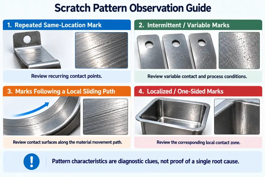
When inspecting defective parts, pressroom personnel use pattern clues to narrow down potential causes before making process or tooling adjustments.
Repeated Scratches in the Same Location
When a scratch appears in the exact same physical location on part after part, it may suggest recurring contact or tool-surface conditions.
- Diagnostic Value: Indicates that a specific, fixed point on the punch, die radius, stripper, or stock guide is contacting the material in a repeatable manner.
- Potential Causes: Localized metal pickup (galling), a chip or nick on a draw die radius, a raised grinding ridge, or a damaged stock guide.
- Caution: A repeating mark suggests a localized tooling contact point, but physical verification of the tool surface is necessary to determine whether the root cause is adhesive pickup, abrasive tool damage, or localized clearance tightness.
Intermittent or Random Scratches
Scratches that appear sporadically—varying in position, length, and frequency across a production run—may direct attention toward variable process conditions rather than a single fixed contact point.
- Diagnostic Value: May suggest that the source is moving, accumulating inconsistently, or changing with process conditions.
- Potential Causes: Loose environmental contamination, floating metal slivers, inconsistent lubricant application, shifting mill scale, or temporary debris trapped on the blank.
- Caution: Intermittent marks do not completely rule out galling; initial stages of adhesive transfer can produce variable scratching before pickup becomes permanently bonded to the tool steel.
Scratch Direction
The orientation of a surface scratch relative to the material movement path provides important context regarding when and where the mark was created:
- Marks Aligned With Material Movement: Scratches that follow the local sliding direction may justify closer inspection of contacting tool surfaces, guides, or forming zones along that path.
- Transverse or Angular Marks: Marks that do not follow the expected local sliding direction may justify checking feeding, upstream material contact, or handling conditions in addition to the die itself.
Directional clues can help prioritize where to inspect, but they should be combined with part location, repeat frequency, and direct examination of the corresponding contact surfaces.
One-Sided or Localized Marks
Surface marks confined to one side of a part or localized near a specific forming zone may suggest a localized contact, alignment, lubrication, or surface-condition issue. The corresponding tool area should be inspected before assigning a root cause.
Tool-Side Pickup vs. Part-Side Surface Damage
A fundamental step in resolving friction defects is recognizing the physical relationship between tool-surface condition and part-surface geometry:
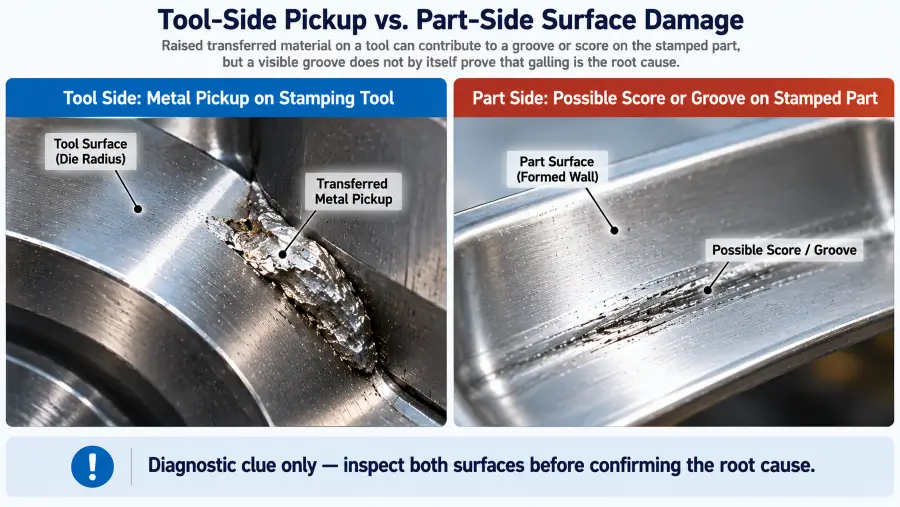
- Tool Side: Characterized by a raised accumulation of transferred workpiece material (pickup) bonded to the die radius or punch wall.
- Part Side: Characterized by a depressed groove, gouge, or score line dragged into the sheet metal by the raised tool pickup.
Although a raised pickup on the tool can produce a corresponding groove or score on the part, one condition does not prove the other without physical inspection.
For example, a deep groove on a stamped part can be produced by a sharp, chipped edge on a tool steel matrix without any material pickup present. Conversely, early-stage, thin material pickup on a die radius may leave light burnished tracks without carving deep grooves into the sheet. Accurate diagnosis requires inspecting both the workpiece and the contacting tool surface.
How to Troubleshoot Galling and Surface Scratches
When surface defects appear during production, pressroom teams systematically review process variables to identify contributing factors. The following table outlines diagnostic starting points for common surface-defect observations.
| Observed Pattern | Possible Contributors | What to Review |
|---|---|---|
| 1. Repeated line in same area | Tool pickup, localized roughness, or another recurring contact point. | Inspect the corresponding tool-contact zone; review surface condition and local lubricant coverage. |
| 2. Random isolated scratches | Loose debris, contamination, intermittent pickup, or variable material contact. | Review material cleanliness, contact surfaces, and where contamination could enter the process. |
| 3. Visible pickup on tool | Adhesive material transfer may be present. | Review the affected contact surface, lubricant condition, and material-to-tool interaction. |
| 4. Scoring increases during production | Growing pickup or changing lubrication/contact conditions. | Compare mark progression with tool-surface condition and lubricant consistency. |
| 5. Scratch begins after maintenance or setup change | Altered surface condition, alignment, lubricant condition, or another setup-related change. | Review the specific changes made before the defect appeared. |
| 6. Material-specific recurrence | Material/tool interaction, coating transfer, or lubricant compatibility may be contributing. | Review material type, surface condition, lubricant behavior, and the corresponding contact zone. |
Using this diagnostic framework can help operators and tooling engineers narrow the investigation before taking corrective action.
General Industry Approaches to Reduce Galling
Reducing adhesive wear generally involves reviewing the contact conditions at the tool-material interface. General industry approaches may include the following:
Improve Lubrication Conditions
Lubrication conditions are one important area to review when adhesive wear occurs:
- Lubricant Selection: Lubricants intended for demanding forming conditions may use boundary or extreme-pressure additive systems to help maintain separation at the interface.
- Application Uniformity: Consistent lubricant coverage can help reduce dry areas that promote direct metal contact.
- Operating Suitability: Lubricant behavior should be evaluated for the material, forming severity, temperature, and contact conditions of the specific application.
Review Tool Surface Condition
Tool surface topography significantly affects lubricant retention and friction:
- Surface Finish: Tool surface finish can affect both friction and lubricant retention. The appropriate finish depends on the material, lubricant, and forming operation, so a universal roughness value should not be applied.
- Localized Surface Irregularities: Nicks, rough transitions, or other local surface irregularities should be reviewed where they coincide with the defect location.
If the observed surface condition may reflect broader tooling deterioration rather than localized pickup alone, see our guide to stamping die wear for warning signs, wear mechanisms, and maintenance decisions.
Remove Existing Pickup Carefully
When metal pickup is confirmed, the affected tool surface may require corrective attention before stable production can resume:
- Targeted Correction: General industry practice may involve removing transferred material without unnecessarily altering the intended tool geometry.
- Preserving Tool Geometry: Corrective work should avoid unintentionally changing critical tool geometry or contact conditions.
Surface Treatments and Tool Coatings
For severe forming applications or difficult materials, surface engineering options are evaluated across the industry:
- PVD / CVD Coating Concepts: Coatings such as TiCN, CrN, or DLC are examples of surface-engineering options used in some applications to modify friction, hardness, or material affinity at the contact surface.
- Other Surface Treatments: Nitriding and related treatments are also used in some tooling applications, depending on tool material and process requirements.
(Note: Surface coatings and specialized heat treatments are evaluated as general industry engineering options based on specific job requirements.)
Review Contact Conditions
Contact conditions can also be reviewed where galling remains localized to a specific forming area:
- Tooling Geometry: Local radii and contact geometry can influence pressure and sliding severity and may need application-specific review. Broader metal stamping design guidelines cover DFM considerations beyond this galling-specific contact review.
- Contact Load: Local restraining or holding conditions can influence interface pressure and lubricant retention and should be evaluated in the context of the specific forming operation.
- Sliding Contact Length: Where applicable, tool geometry that changes the amount of sliding contact may influence friction and pickup behavior.
How to Prevent Surface Scratches During Stamping
Reducing non-galling surface scratches involves controlling contamination and reviewing the surfaces that contact the material:
- Maintain Clean Contact Surfaces: Keep relevant tool and material contact surfaces free of loose slivers, scale, and other contamination.
- Control Incoming Surface Contamination: Review whether dirt, scale, coating debris, or other particles are entering the contact zone with the material.
- Ensure Lubricant Consistency: Review lubricant coverage and contamination where scratch patterns change during production.
- Review Pickup Development: If marks become progressively stronger, inspect the corresponding tool-contact area for developing material transfer.
- Review Handling Contact: Where marks may occur outside the forming zone, inspect feeding, transfer, and part-handling contact points.
- Distinguish Root Causes: Compare recurring and random marks before deciding whether tooling modification, cleaning, lubrication review, or another corrective action is appropriate.
- Avoid Universal Fixes: Recognize that no single lubricant, coating, or polishing rule solves all surface defect issues; solutions must match the specific alloy, tool design, and press conditions.
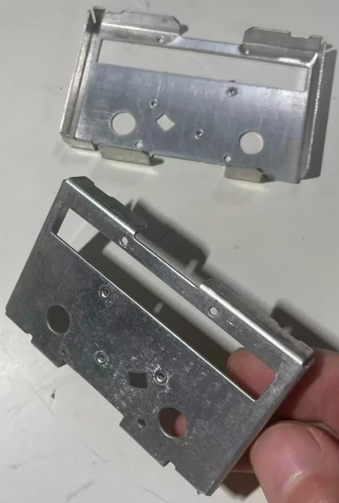
Real Production Perspective: Light Surface Scratches on an Aluminum Electrical Component
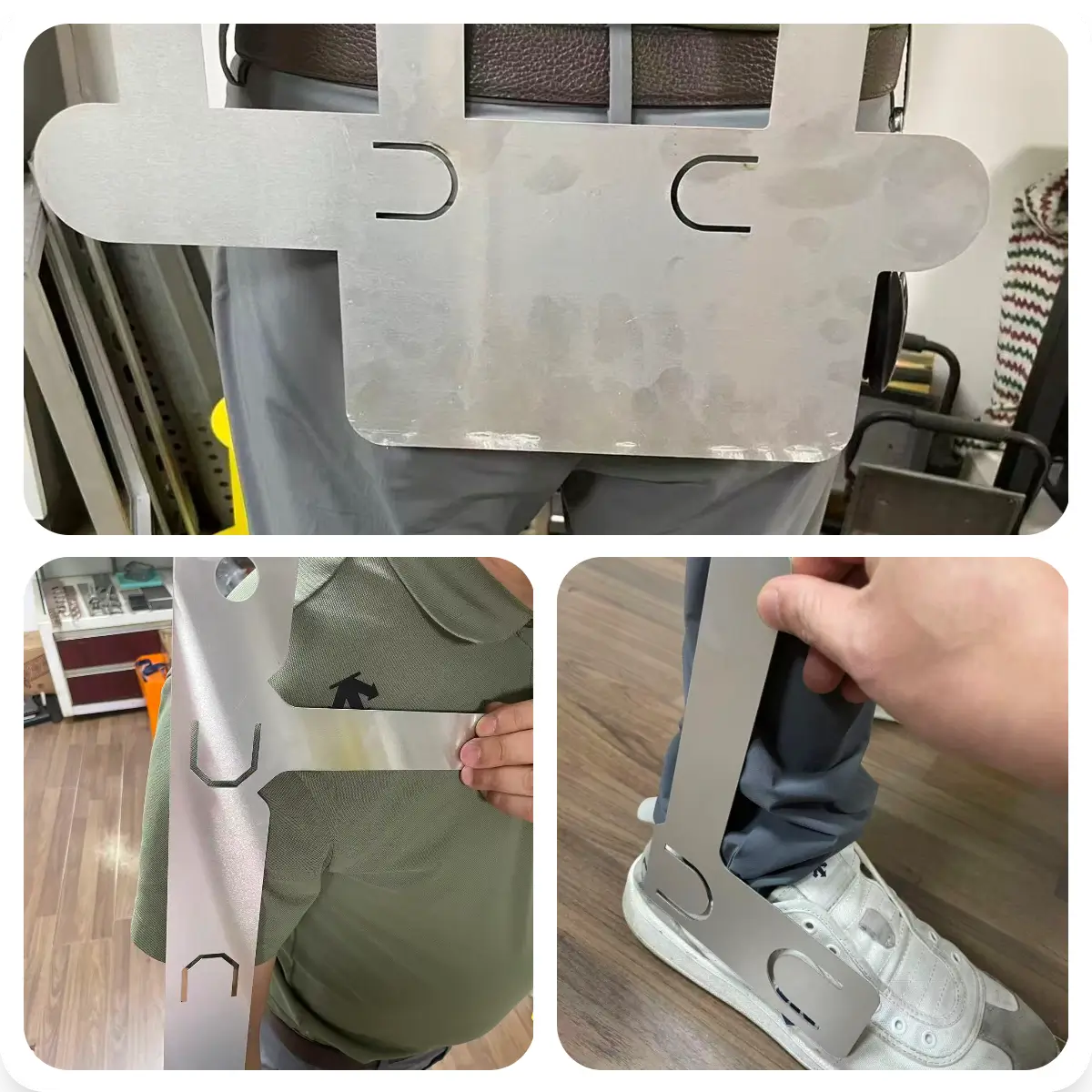
In one Metal Stamp Factory project, an aluminum stamped component used in electrical heat-dissipation equipment required multiple pierced features, including several relatively small holes, together with formed edges and structural features.
After stamping and forming, light surface scratches could be observed on some areas of the aluminum part. For this type of component, visible marks do not automatically prove that galling has occurred. Aluminum surfaces can pick up marks from several contact conditions during punching, forming, feeding, handling, or interaction with tooling surfaces.
The practical troubleshooting approach is therefore to compare where the marks appear, whether they repeat in the same location from part to part, and whether corresponding material pickup or surface irregularities can be found on the contacting tooling. Lubricant condition, material cleanliness, tooling contact surfaces, and handling conditions should also be reviewed before assigning a root cause.
This production example illustrates an important distinction in surface-defect diagnosis: a real stamped part may show visible scratches or drag marks without the appearance alone proving adhesive galling. The surface mark is the symptom; the underlying mechanism still needs to be confirmed through process and tooling review.
What OEM Buyers Should Ask When Galling or Surface Scratches Occur
When surface quality issues arise during OEM part manufacturing, clear communication between procurement teams, quality engineers, and stamping suppliers is critical. The following questions help structure a technical review:
- Where on the part does the surface damage appear?
- Purpose: Helps identify which contact zone should be inspected first.
- Does the mark repeat in the same location on multiple parts?
- Purpose: Helps compare recurring contact conditions with more variable contamination or handling-related causes.
- Is visible material pickup present on the contacting tool surface?
- Purpose: Helps determine whether visible tool-side material transfer is present or whether another surface-damage mechanism should be investigated.
- Did the issue begin after a material, lubricant, setup, or tooling change?
- Purpose: Helps correlate the start of the defect with a recent material, lubricant, tooling, or setup change.
- Is the problem material-specific?
- Purpose: Helps determine whether material-to-tool interaction may be contributing to the problem.
- Are the marks continuous, intermittent, or isolated?
- Purpose: Helps compare recurring sliding-contact conditions with more intermittent contamination or handling-related factors.
- How was the corrective action verified before production resumed?
- Purpose: Confirms that the corrective action was checked through appropriate metal stamping quality inspection on both the part and the relevant tool-contact area before production resumed.
Frequently Asked Questions
1. What causes galling in metal stamping?
Galling occurs when adhesive material transfer develops during sliding contact under unfavorable friction, pressure, and lubrication conditions. When the lubricant film becomes less effective, local metal-to-metal contact may increase. Under unfavorable friction and pressure conditions, localized adhesion or micro-welding can occur, allowing small amounts of workpiece material to transfer to the tool and form pickup that may score later parts.
2. What is the difference between galling and surface scratching?
Galling is a specific adhesive wear mechanism involving metal transfer and pickup buildup on tooling. A surface scratch is a general visual term for any linear gouge, score, or line on the sheet metal. While galling produces severe scratches, surface scratches can also result from rough tooling finishes, trapped debris, scale, or handling damage without adhesive metal transfer occurring.
3. Why does metal stick to stamping dies?
Metal may stick to stamping dies when local contact conditions allow direct interaction between the workpiece and tool surface, especially where lubrication becomes less effective. Under severe sliding friction, chemical affinity between the metals promotes micro-welding. Once initial material transfers to the tool face, subsequent strokes deposit additional material onto the spot, growing the pickup.
4. Why do stamped parts develop repeated scratch marks?
Repeated scratch marks in the same location may suggest a recurring contact point in the tooling or material path. This can be caused by bonded metal pickup (galling), a nick or chip on a die radius, a raised grinding ridge, or a misaligned stock guide. Physical inspection of the corresponding tool surface is necessary to confirm the exact contact cause.
5. How can galling be prevented in metal stamping?
Reducing galling risk involves managing lubrication, tool-surface condition, material-to-tool interaction, and local contact severity. General industry options may also include surface treatments or tool coatings where appropriate for the application.
About Metal Stamp Factory
Metal Stamp Factory was established in 2014 in Xiamen, China, focusing on custom metal stamping, tooling development, and precision hardware manufacturing for OEM projects. The founder of Metal Stamp Factory, Shengtong Chen, started learning mold making and metal stamping at the age of 17 and has accumulated more than 25 years of hands-on manufacturing experience in tooling development, metal stamping, and OEM production.
When addressing surface finish challenges or potential galling concerns, our engineering approach is to review material conditions, tooling contact surfaces, lubricant selection, visible pickup development, surface contamination controls, and press setup parameters before deciding on corrective action. This helps keep the investigation focused on the actual contact conditions instead of assuming that every visible scratch has the same cause.